23
Basic Operation (Screen Display and Layout)
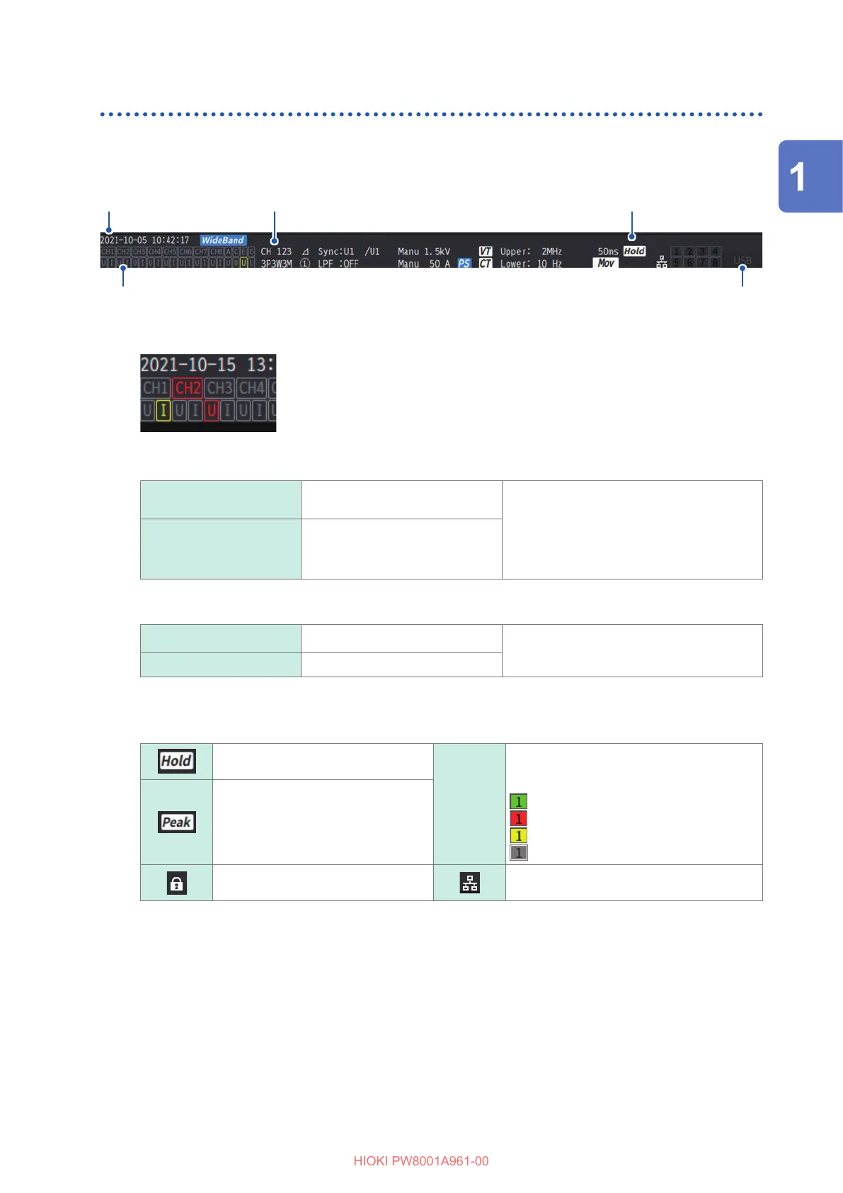
Common screen display
The following is an example screen. Actual screens vary depending on the instrument’s settings.
This section describes the screen elements that are shown on all screens.
Date and time
Warning indicator*
1
Media indicator*
3
Operating state indicator*
2
Setting indicator (p. 24)
*1: Warning indicator
Example, the Ch. 1 current input is in an overloaded condition (yellow), Ch. 2 is
in a synchronization-unlocked condition (red), and the Ch. 3 voltage input is in a
peak-over condition (red).
The top row displays the synchronization state for each input channel.
CH1, CH2, CH3, CH4,
CH5, CH6, CH7, CH8
Analog DC input of input channels
and motor input channels
Gray: Installed channels
Red: Channels in a synchronization-
unlocked condition
Yellow: Channels in a synchronization-
unlocked condition for harmonics
analysis only
A, C, E, G Motor input channels
The bottom row displays the range-peak-over state for each input channel.
U Voltage input
Gray: Normally measured.
Yellow: An overload condition occurs.
Red: A peak exceeds the threshold.
I Current input
*2: Operating state indicator
In the hold state
[1][2][3][4]
[5][6][7][8]
Displays the operation status of each
channel in the following colors during
integration measurement. (p. 64)
(green) Integration starts.
(red) Integration stops.
(yellow) Integration standby
(colorless) Data reset
In the peak hold state
Key locked
When connected to a network via the LAN
interface
*3: Storage media indicator
Usage of the USB ash drive is indicated using a level meter.
The indicator lights up in red if the free space rate of the drive reduces to less than 25% or ERROR occurs.
Overview

 Loading...


