49
Checking Connections
2.9 Checking Connections
Based on the measured values and vectors on the screen, you can check whether the voltage
cords and the current sensors are connected properly.
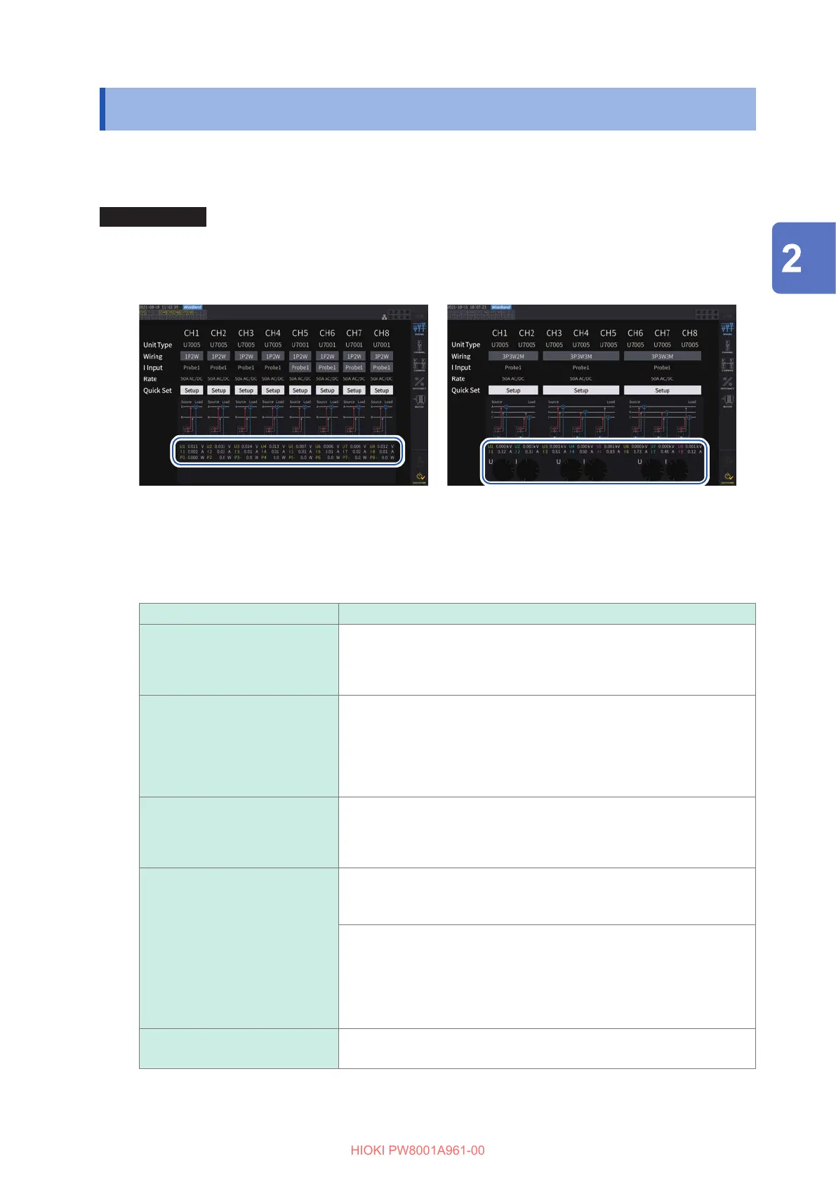
Display screen [INPUT] > [WIRING]
1P2W mode
When the cords and sensors are properly
connected, the measured values are displayed.
Wiring mode other than 1P2W mode
The measured values and vector lines are displayed.
When the cords and sensors are properly connected,
the vector lines indicates the proper range.
• The vector lines are shown in the same colors as those of measured values’ items.
• The indication range used in vector diagrams assumes an inductive load (such as a motor).
• Vectors may exit the range when the power factor approaches zero or when a capacitive load is
measured.
• The measured value of active power P for individual channels may be negative for 3P3W2M and 3V3A
lines.
Problem Cause
The measured voltage value is
too high or too low
• The voltage cord connectors have insuciently been inserted into the
instrument’s voltage input terminals.
• The voltage cords have improperly been connected to the lines under
measurement.
The measured current value is
not appropriate.
• The current sensor connectors have insuciently been inserted into
the instrument’s current sensor input terminals.
• The current sensors have improperly been connected to the lines
under measurement.
• The Probe 1 and Probe 2 settings have not matched the terminals into
which the current sensors’ connectors have been inserted.
The measured active power
value is negative.
• The voltage cords have improperly been connected to the lines under
measurement.
• The current sensors’ current direction mark (arrow) have not pointed at
the load side but the source side.
The vector arrow is too short or
the vector lengths dier.
For voltage vectors
• The voltage cords have improperly been connected to the lines under
measurement.
For current vectors
• The current sensors have improperly been connected to the lines
under measurement.
• The connected current sensors are inappropriate for currents owing
through the line under measurement.
• The [Sync. source] setting has been set improperly.
The vector direction (phase) and
color dier.
• The voltage cords and current sensors have been connected to the
inappropriate terminals.
See “2.2 Connecting the Voltage Cords (Voltage Input)” (p. 33), “2.3 Connecting the Current Sensors (Current
Input)” (p. 34), and “2.8 Connecting Measurement Leads and Sensors to Lines to Be Measured” (p. 47).
Preparing for Measurement

 Loading...


