53
Measuring Power
3.2 Measuring Power
The basic screen is used to view measured power values for each lines under measurement. The
screen provides functions for listing measured power values for each specied wiring conguration
and displaying measured voltage and current values in detail.
You can change the on-screen channels using the channel-selection keys as well as the voltage
and current range.
Press the [MEAS] key, then tap [VALUE] > [BASIC], and then select the basic screen.
Select [P] (power screen), [U] (voltage screen), [I] (current screen), or [Integ.] (integration screen)
from the screen icons.
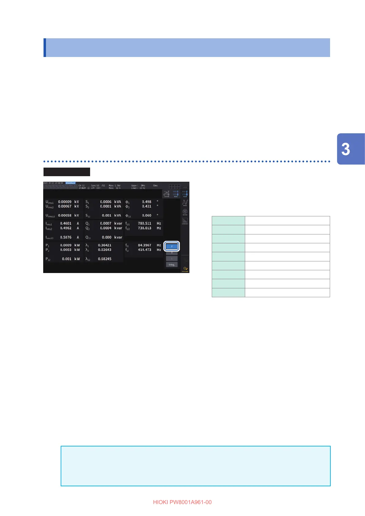
Displaying measured power values
Display screen [MEAS] > [VALUE] > [BASIC]
11
1
Tap [P].
2
Switch the displayed channel using the
CH keys for channel selection.
Urms
Voltage RMS value
Irms
Current RMS value
P
Active power
S
Apparent power
Q
Reactive power
λ
Power factor
Φ
Power phase angle
fU
Voltage frequency
fI
Current frequency
• Depending on the rectication setting, mean-value rectied RMS equivalent values (mean values) will be
displayed in the voltage RMS value (Urms) and current RMS value (Irms) display areas.
See “Rectication method” (p. 62).
• Polarity signs for power factor (
λ
), reactive power (Q), and power phase angle (
φ
) indicate the lead/lag
polarity, with no sign indicating lag and a minus sign (−) indicating lead.
• The polarity sign for fundamental wave power factor (
λ
fnd) and fundamental wave reactive power (Qfnd),
which are calculated using measured harmonic values, indicates the sign of the calculation, which is the
opposite of the signs of power factor (
λ
) and reactive power (Q). (when the power equation is set to Type 1)
See “10.5 Specications of Equations” (p. 212).
• The polarity sign for power factor, reactive power, and power phase angle may not stabilize when there is a
large dierence between the voltage and current levels or when the power phase angle approaches 0
°
.
• In 3P3W2M or 3V3A wiring mode, active power (P), reactive power (Q), apparent power (S), and power
factor (
λ
) are undened for all channels. Use only the sum value*.
*: When using a connection other than 1P2W, measured power value calculated as the sum of measured
values of at least two channels (for example, P123, S456, Q34).
IMPORTANT
Measured values may be displayed for channels without input due to the eects of surrounding
noise. Due to induced voltage, displayed values may become unstable with no input; however,
this is not a malfunction.
Displaying Power Numerically

 Loading...


