246
Block Diagram
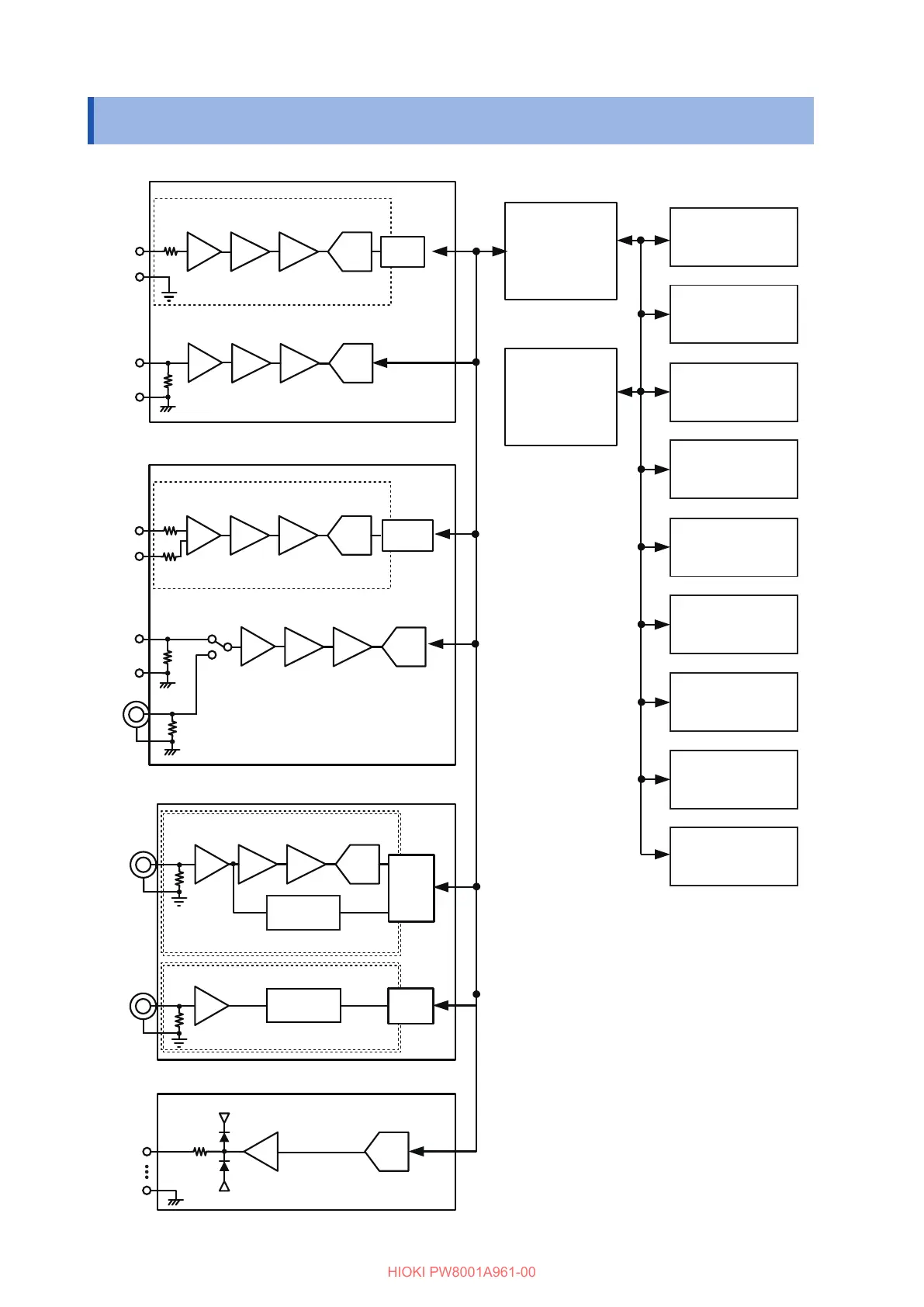
11.9 Block Diagram
D/A
100 Ω
CPU
RS-232C
LAN
GP-IB
Range
A/D
1 MΩ
LPF
1 kHz, 20 kHz, 100 kHz
Isolator
BNC
1 MΩ
Isolator
BNC
U
±
A/D
4 MΩ
LPF
A/D
1 MΩ
LPF
I
±
Isolator
Off, 2 MHz
Off, 2 MHz
U
±
Range
A/D
1 MΩ
LPF
Range
A/D
1 MΩ
LPF
I1
±
Isolator
I2
±
1 MΩ
BNC
Off, 500 kHz
Off, 500 kHz
1 MΩ
Range
Range
Ch. 1 to
Ch. 20
U7005 15MS/s input circuit
U7001 2.5MS/s Input circuit
Voltage input circuit
Isolation
Current sensor input circuit
Voltage input circuit
Current sensor input circuit
Isolation
Each channel isolated
Each channel isolated
Motor analysis input circuit (optional)
D/A output circuit (optional)
Ch. A, C, E, G input circuit
Ch. B, D, F, H input circuit
10.1″ WXGA LCD
(touchscreen)
Keys
USB port
(ash drive)
Synchronization
control BNC
CAN/CAN FD
(optional)
Synchronization
control Opt ber
(optional)
High-speed
power analyzing
engine III
Zero-crossing
detection
Zero-crossing
detection

 Loading...


