27
System Architecture
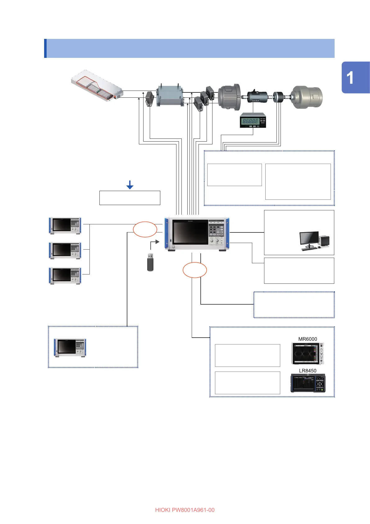
1.5 System Architecture
Subordinate
Subordinate
Subordinate
Master
Subordinate
Up to 4 units
Battery Inverter Torque
sensor
Pulse
encoder
Motor
Communication interface
Computer, controller, etc.
External control
Start, stop, and reset
integration.
BNC cable
Optical synchronization
CAN/CAN FD option
HILS system
LAN
GP-IB
RS-232C
Waveform and D/A output option
Waveform output
Oscilloscope
Memory HiCorder
Analog output
Data logger
Comparator
Up to 2 units
Optical link option
Motor analysis option
Motor input
Torque sensor
Encoder signal
External input
Solarimeter output
Thermometer analog output
Pulse signal
Waveform trigger
BNC synchronous interface
U7001 2.5MS/s Input Unit
U7005 15MS/s Input Unit
Voltage input, up to 8 channels
Current sensor input, up to 8 channels
Optical cable
Either one
Either one
• Motor analysis, CAN/CAN FD, waveform and D/A output, and optical link are optional.
• The BNC synchronization and the optical link interface cannot be used simultaneously.
• The waveform and D/A output option and the CAN/CAN FD option cannot be installed
simultaneously.
Overview

 Loading...


