58
Measuring Power
Synchronization source
This section describes how to set the source for each wiring conguration, which determines the
period (between zero-crossing points) that serves as the basis for various calculations.
In general use, select the measurement channel’s voltage for channels measuring AC current or
[DC] for channels measuring DC current.
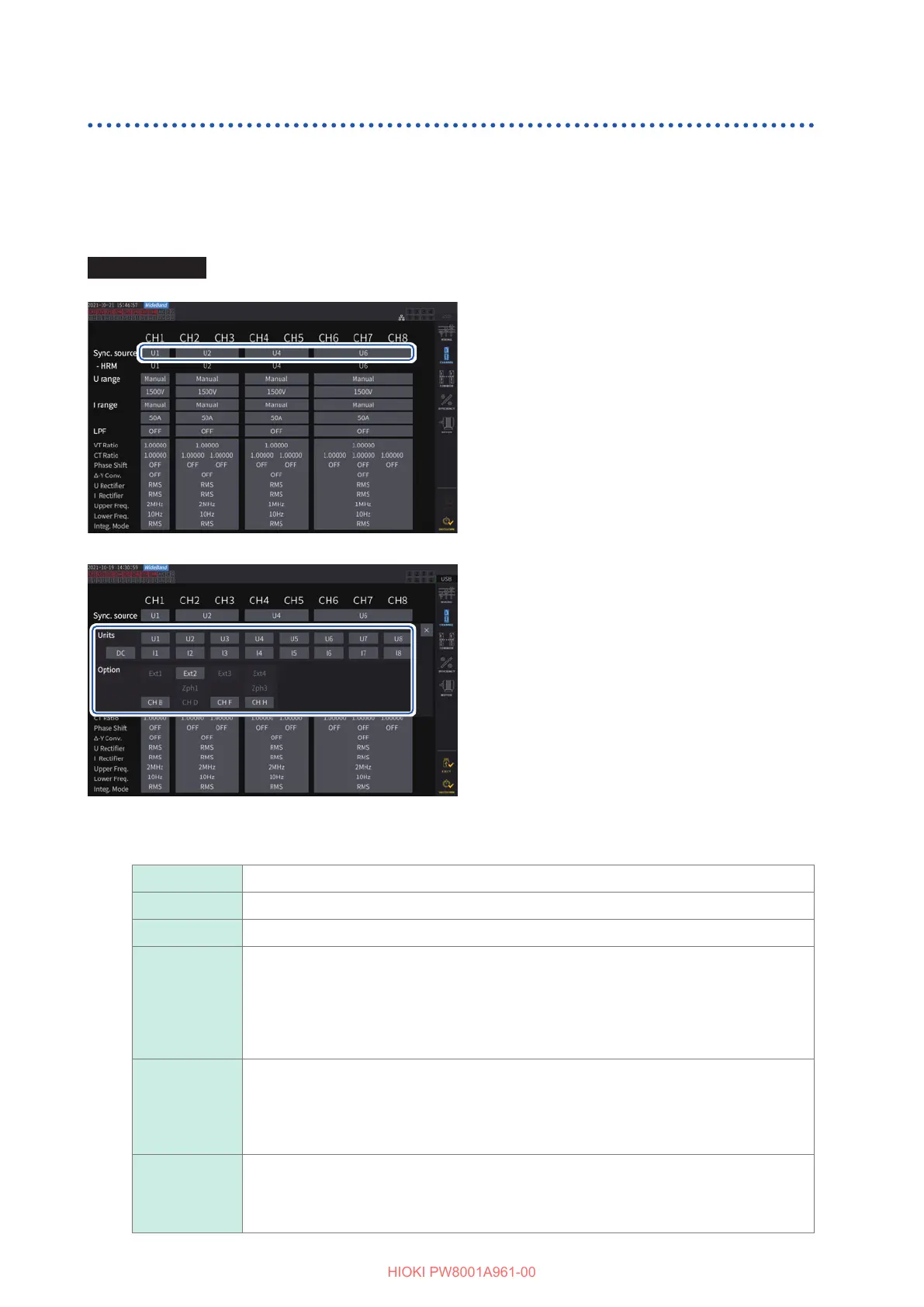
Display screen [INPUT] > [CHANNEL]
11
1
Tap the [Sync. source] box of the
wiring conguration you wish to set to
open the setting window.
The set synchronization source will be
displayed by the [Sync] setting indicator at the
top of the Measurement screen.
2
Tap a synchronization source module
to select it.
22
Synchronization source module
U1 to U8 Set this when performing measurement with respect to a voltage signal.
I1 to I8 Set this when performing measurement with respect to a current signal.
DC Set this when performing measurement with respect to the data refresh interval.
Ext1 to Ext4
This may be used be set when the input settings of the following channels of the
motor analysis-equipped model are [Speed] (pulse input) and the remainder of
{(pulse count) / [(Number of poles) / 2]} is zero.
Ext1: Ch. B, Ext2: Ch. D, Ext3: Ch. F, Ext4: Ch. H
Set this for measurement with respect to a pulse pulses in motor analysis or when
measuring electrical angles.
Zph1, Zph3
This can be set when the input settings of the following channels of the motor analysis-
equipped model are [Origin] (pulse input).
Zph1: Ch. D, Zph3: Ch. H
Set this if you wish to obtain measurement results synchronized to one cycle of the motor’s
mechanical angle during motor analysis.
CH B, CH D,
CH F, CH H
This may be used be set when the operation mode of the relevant channel of the motor
analysis-equipped model is [Individual] mode.
Set this when you wish to perform measurement synchronized to an external signal (pulse
input).

 Loading...


