47
Connecting Measurement Leads and Sensors to Lines to Be Measured
2.8 Connecting Measurement Leads and Sensors to
Lines to Be Measured
Perform zero adjustment, and then connect voltage cords and current sensors to lines to be
measured as indicated in the wiring diagram shown on [INPUT] > the [WIRING] screen. To ensure
accurate measurement, connect the instrument exactly as shown on [INPUT] > the [WIRING]
screen.
The wiring diagram will be displayed when you select a wiring mode on [INPUT] > the [WIRING]
screen.
See “2.5 Setting Wiring Mode and Conguring Current Sensor Settings” (p. 41).
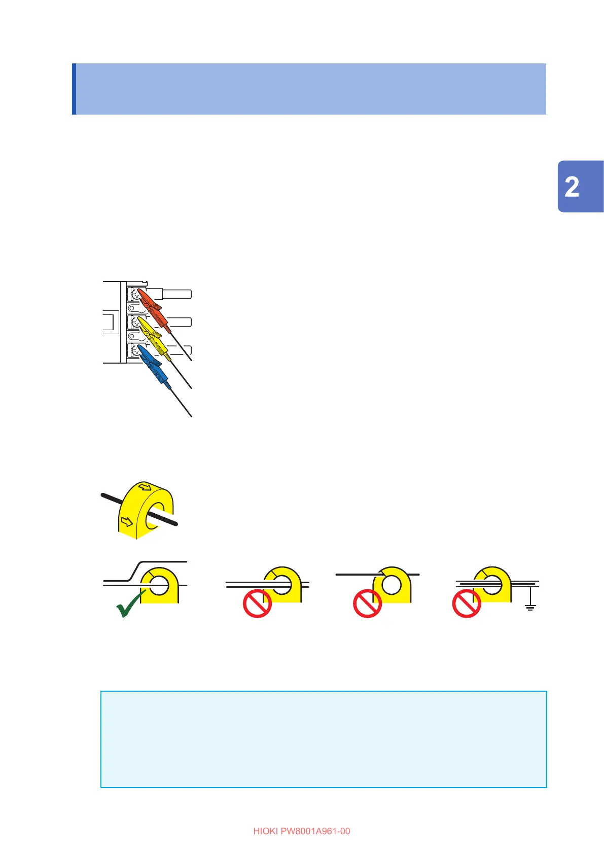
Voltage Cord
Firmly clip the voltage cords to the metallic parts on the power supply
side, such as screws and bus bars
Current sensor
Source
Load
Clamp the current sensor so that its current direction mark points at the
load side.
OK
NO
NONO
Do not clamp the sensor
around two or more conductors.
Do not pinch the conductor. Do not clamp the
sensor to a shielded
wire.
IMPORTANT
• The phases are labeled as A, B, C on the wiring diagram screen. Connect the instrument based
on whatever names you are using, such as R/S/T and U/V/W, as appropriate.
• Clamp the sensor around only one conductor. Clamping the sensor around two or more of
conductors in a bundle prevents the instrument from measuring any current regardless of
whether the measurement target is a single-phase or three-phase circuit.
Preparing for Measurement

 Loading...


