84
Motor Measurement (Motor Analysis-Equipped Model)
Conguring the motor input settings
Connect torque sensors and tachometers by referring to “Motor measurement wiring” (p. 78).
Congure the motor analysis settings based on those connections.
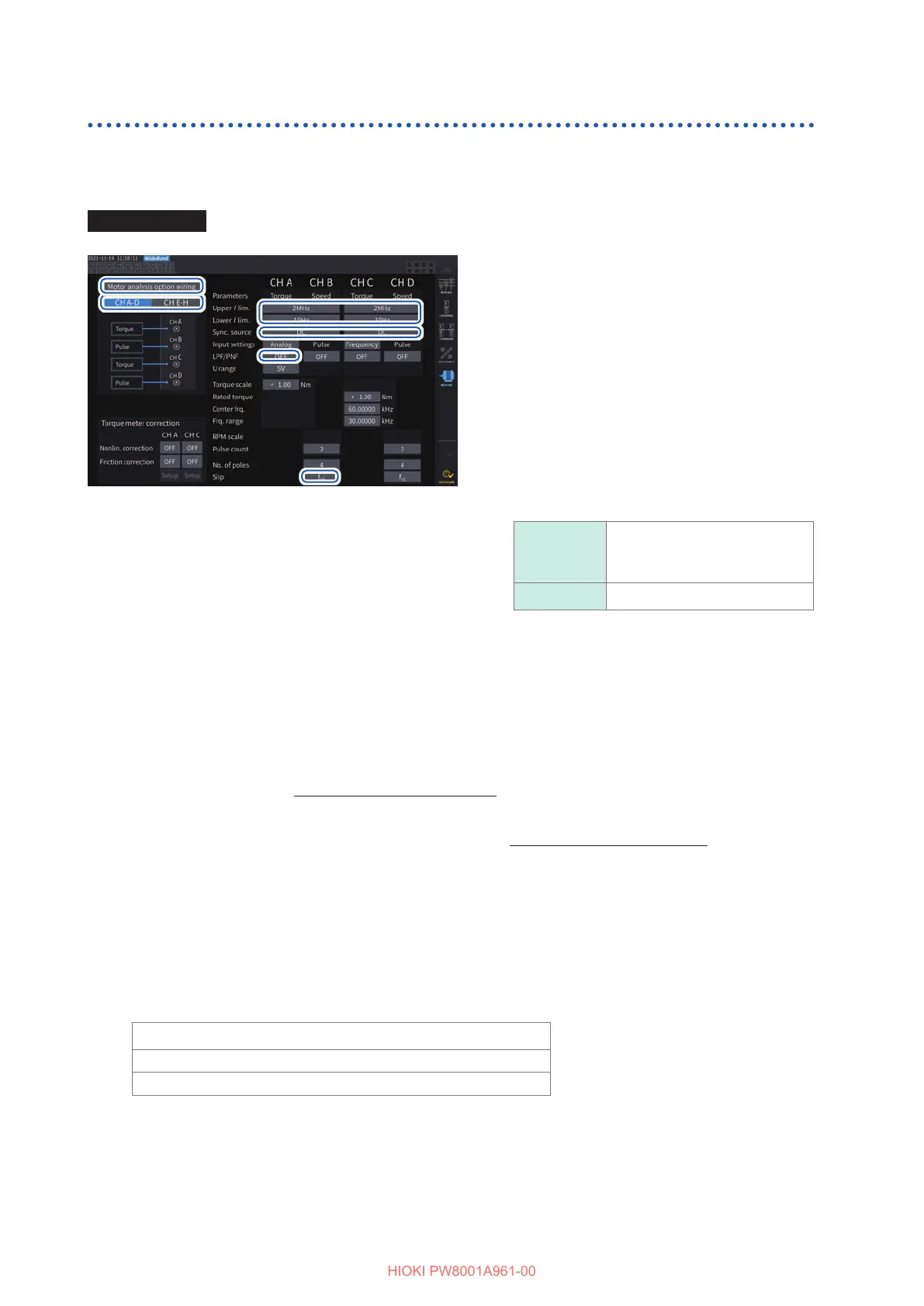
Display screen [INPUT] > [MOTOR]
11
33
44
55
66
22
1
Tap [Motor analysis option wiring] to
select.
2
Tap [CH A-D] or [CH E-H] to display
channels you wish to change the
settings.
3
Tap the [Upper f lim.] and [Lower f lim.]
box, and select the frequency from the
list.
Set this when pulses are to be input for the
motor input.
Upper f lim.
100 Hz, 500 Hz, 1 kHz, 5 kHz,
10 kHz, 50 kHz, 100 kHz,
500 kHz, 1 MHz, 2 MHz
Lower f lim. 0.1 Hz, 1 Hz, 10 Hz, 100 Hz
Upper frequency limit
This setting species the lowest frequency that exceeds the maximum frequency of the input pulse signal.
When [Motor analysis option wiring] is set to [Individual Input], the setting is used as the upper limit for
D/A output.
When using motor analysis mode, this setting is used as the pulse frequency that is used to display RPMs and
motor powers and as a pulse frequency to calculate the upper limit value for the D/A output.
(RPM upper limit value) =
60
×
(Set upper frequency limit)
(Pulse count setting)
(Motor power upper limit value) = (Maximum torque value)
×
2
×
π
×
(RPM upper limit value)
60
If the input RMS signal setting is [Analog], the RMS upper limit is calculated by multiplying the scaled RMS
value by the voltage range value.
Lower frequency limit
This setting species the lower frequency limit for measurement of the input pulse signal.
When the following synchronization sources are selected, the lower limit frequency is also used as the lower
frequency limit for measurement.
Ext1, Ext2, Ext3, Ext4
Zph1, Zph3
Ch. B, Ch. D, Ch. F, Ch. H

 Loading...


