43
Setting Wiring Mode and Conguring Current Sensor Settings
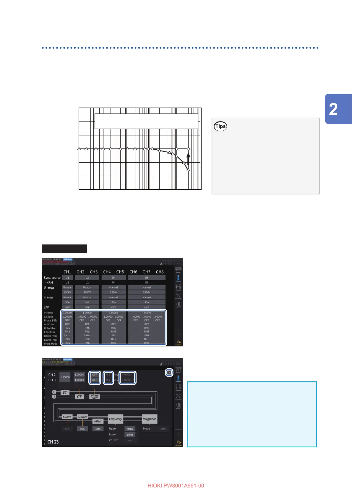
Correcting phase errors for current sensors
Current sensors generally exhibit a tendency for phase error to increase gradually in the high-
frequency region of their frequency band. By using sensor-specic phase characteristics
information to correct the measured values, it is possible to reduce the error component in power
measurement made in a high-frequency region.
Conceptual diagram
Frequency (Hz)
Phase (
°
)
1 M10
−
30
−
20
−
10
0
10
20
30
100 1 k 10 k 100 k
○: Phase characteristics after correction
Δ
: Phase characteristics before correction
Phase correction for current
sensors with auto-recognition
function
When using a current sensor with the
auto-recognition function, the phase of the
current sensor is automatically corrected.
If you wish to set any phase correction
values, follow the steps listed in the
following “How to enter phase correction
values” section.
How to enter phase correction values
For current sensors without the auto-recognition function, it is recommended to perform phase
correction for the current sensor before measurement.
Display screen [INPUT] > [CHANNEL]
11
1
Tap the detailed display area for the
channel to be congured.
2
Tap the [Phase Shift] area box and
select [On].
When using a current sensor equipped with the
auto-recognition function, [Auto] is displayed
as an alternatives. When [Auto] is selected,
the correction values are entered automatically.
3
Tap the frequency box, then enter the
frequency with the numeric keypad.
4
Tap the phase dierence box, then
enter the phase dierence with the
numeric keypad.
5
Tap [
×
] to close the setting window.
IMPORTANT
• Enter the phase correction value accurately.
Invalid settings can cause the correction
process to increase measurement error.
• Operation outside the frequency range within
which the current sensor’s phase accuracy is
specied is not dened.
22 33 44
55
Preparing for Measurement

 Loading...


