92
Motor Measurement (Motor Analysis-Equipped Model)
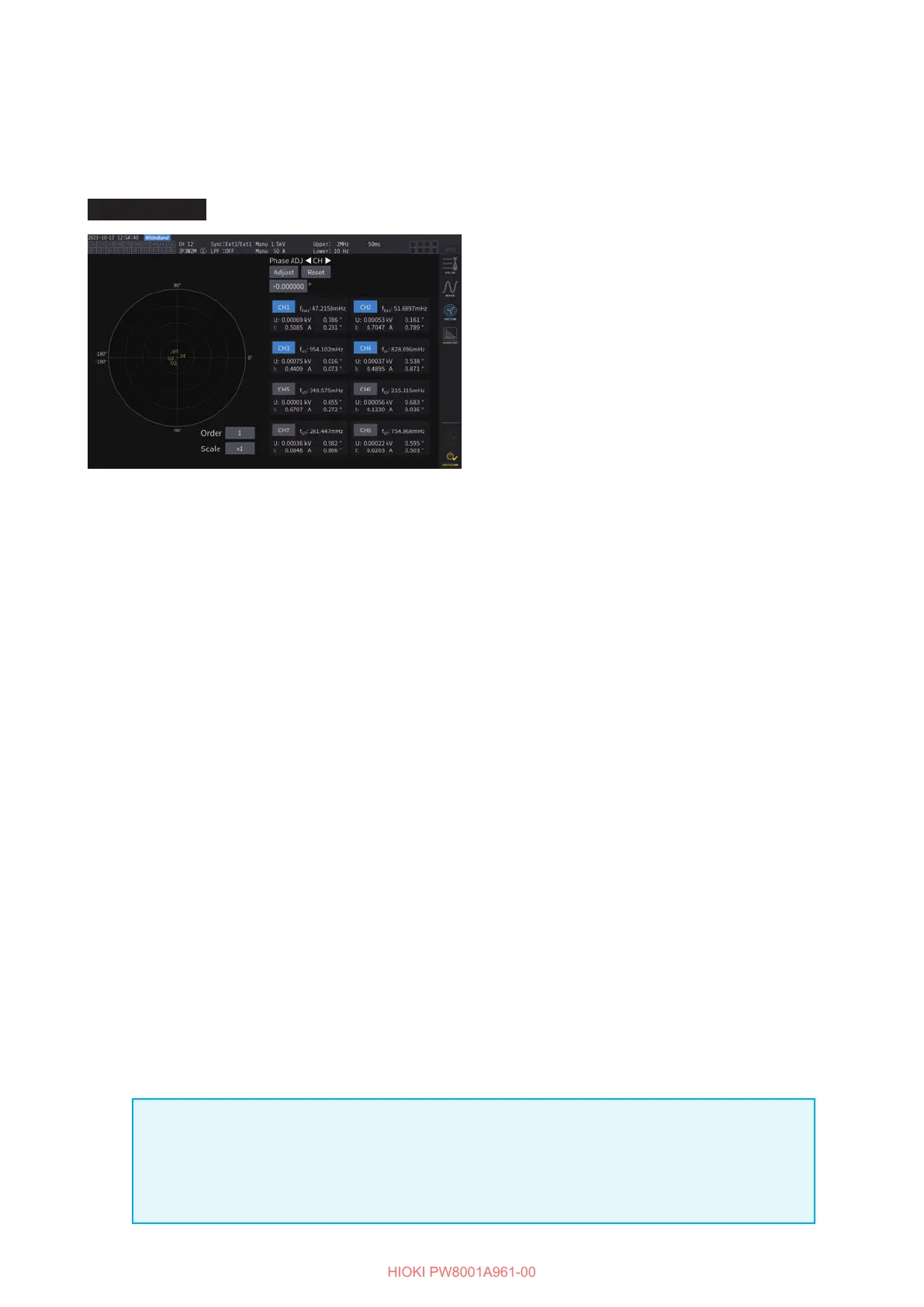
Phase zero adjustment (PHASE ADJ)
This section describes how to zero-correct the phase dierence between the harmonic-measurement
synchronization source’s pulses and the voltage fundamental wave components of the connected
rst channel.
Display screen [MEAS] > [VECTOR]
1
Select the channel for which you
wish to perform phase angle zero
adjustment using the channel selection
keys.
2
To obtain the correction value
according to the input, tap [Adjust]
under [Phase ADJ].
3
To enter a user-dened correction
value, tap the correction value display
area, then enter the correction value
with the numeric keypad window.
• Phase zero-adjustment is available only when the synchronization source is set to [Ext1], [Ext2],
[Ext3], or [Ext4]. Even if keys are operated, phase zero-adjustment has no eect when other
settings are used.
• No key operation is available when the channel is in a synchronization-unlocked condition.
• The correction value has a valid setting range of −180
°
to +180
°
. For the environments where
phase angles are expressed as numbers between 0
°
and 360
°
, convert a correction value into a
number between −180
°
to +180
°
and enter it.
• The correction display area indicates the present correction value for the phase zero adjustment.
Tapping [Adjust] can replace the existing correction value with a new one.
• The set phase zero adjustment correction value will be subtracted from the measured pulse-
based voltage- and current-phase values.
• Correction values will be maintained even if the instrument is turned on or o.
• Tapping [Reset] will clear the correction values and revert to operation in which the instrument
displays the phase dierence with the pulse being used as the reference.
• Correction values will be cleared by the system reset.
Example of electrical angle measurement
1
Rotate the unenergized motor from the load side to measure the inductive voltage
generated across the motor’s input terminals.
2
Perform phase zero adjustment.
Zero adjustment will zero the phase dierence between the fundamental wave component of
the inductive voltage waveform inputted to U1 and the pulse signal.
3
Energize the motor to rotate it.
Voltage and current phase angles measured with the instrument will indicate an electrical
angle based on the inductive voltage phase.
IMPORTANT
Because the phase dierence includes the eects of the rotation input signal’s pulse waveform
and the instrument’s internal circuit delay, it will appear as measurement error when the
instrument measures a frequency that diers greatly from the frequency at which phase zero
adjustment was performed.

 Loading...


