155
Controlling Integration with External Signals
Control signal timing
External control interface signals are detected during the intervals shown on the timing chart below.
Refreshing on-screen information may delay depending on the frequency being measured and the
synchronization state between the instrument and external device.
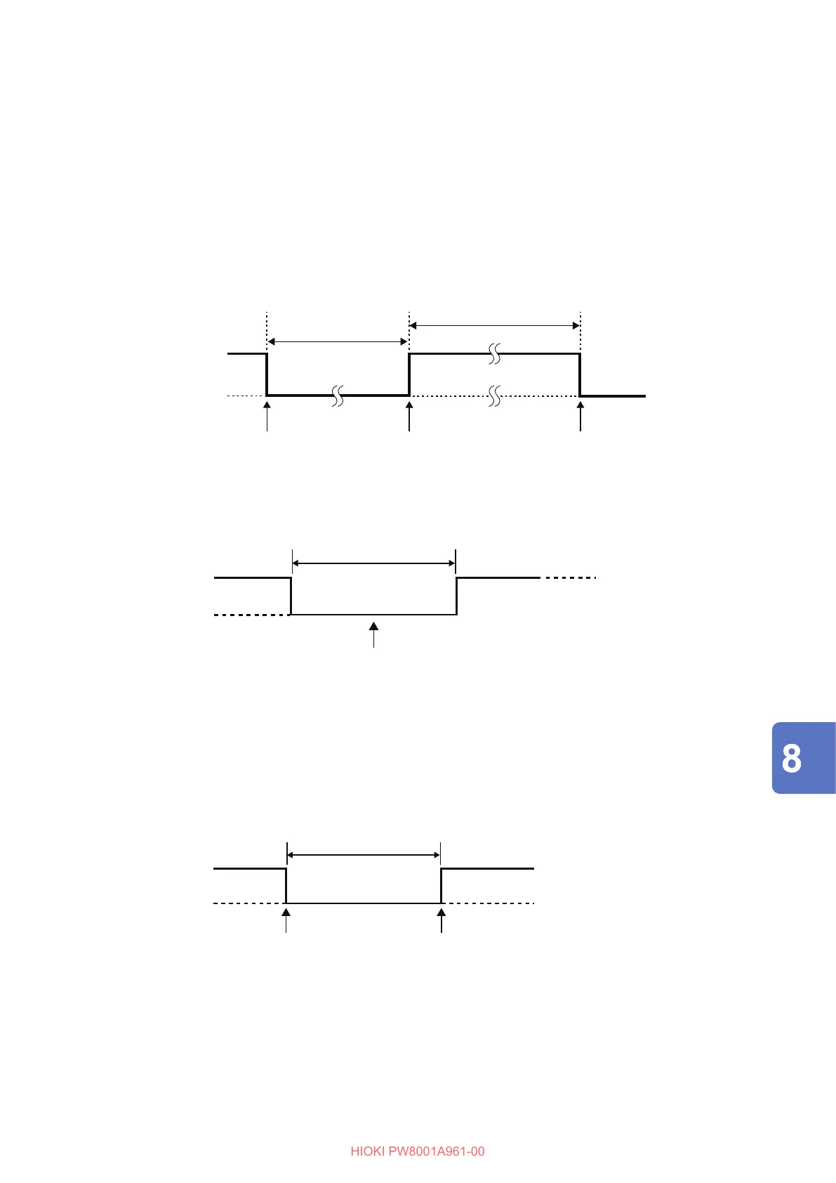
Starting and stopping integration
Using this signal can start/stop integration.
This operation is the same as that performed by the START/STOP key on the instrument’s panel.
5 V (open)
0 V (shorted)
Integration stop Addition startIntegration start
450 ms or more
(When auto-save function is enabled, 1 s or more)
450 ms or more
Resetting integrated values
Using this signal can reset integrated values to zero.
This operation is the same as that performed by the DATA RESET key on the instrument’s panel.
200 ms or more
Integrated values are
reset during this interval.
5 V (open)
0 V (shorted)
This signal is ignored while integration is being performed.
Input this signal at least 450 ms (or at least 1 s when the auto-save operation is enabled) after integration
stops.
Hold
This operation is the same as that performed by the HOLD key on the instrument’s panel.
200 ms or more
Display hold
start
Display hold
cancel
5 V (open)
0 V (shorted)
To avoid instrument damage, do not input a signal at a voltage of 5.5 V or more.
Use chatter-free control signals.
Connecting External Devices

 Loading...


