iZ Technology Corporation
REAR PANEL
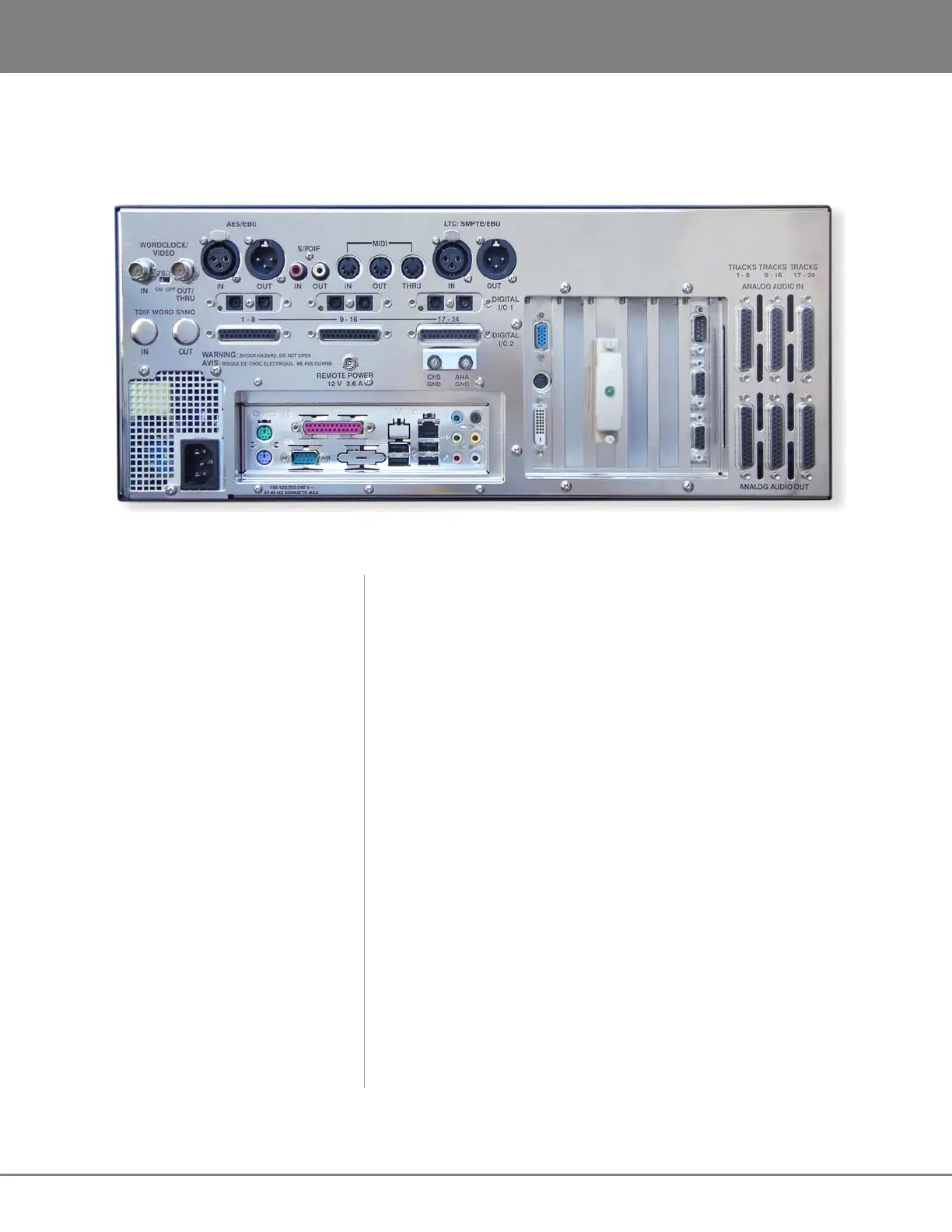
The rear panel of the RADAR provides a wealth of professional sync and audio I/O options.
RADAR
Rear Panel Labeling
(unit shown with optional multi-channel AES/EBU, ADAT and analogue I/O boards)
SYNC REFERENCE
Sync reference signals are input via the WORDCLOCK/VIDEO,
TDIF WORD SYNC, the 2-channel AES/EBU or S/PDIF
connector or the connectors of any installed multi-channel digital
I/O boards. See CONFIGURATION: SYNC REFERENCE for detailed
information.
DIGITAL I/O
All RADAR units are equipped with 2 channels of digital audio I/O
that can utilize either the AES/EBU or S/PDIF interface formats.
Optional multi-channel I/O cards are available for the AES/EBU,
TDIF, ADAT LIGHTPIPE and MADI formats. See
CONFIGURATION: DIGITAL I/O for detailed information.
POSITIONAL (TIMECODE) SYNC
Both MTC (MIDI Timecode) and LTC (SMPTE) can be used for
positional synchronization. See CONFIGURATION: TIMECODE for
detailed information.
CARD CAGE
The card cage contains the SVGA, external SCSI, 9-pin and
RADARLink connectors. See SYSTEM SETUP: MAKING
CONNECTIONS for detailed information.
MOTHERBOARD I/O
The motherboard includes onboard Gigabit Ethernet, (4) USB 2.0,
(2) PS/2 connectors and (1) Serial remote port.
ANALOGUE I/O
The optional analogue I/O boards use six female 25-pin D-Sub
connectors to provide 24 channels of balanced audio I/O. See
SYSTEM SETUP: MAKING CONNECTIONS for detailed information.