AKD2G-S Installation Manual, Safety 1 | 8 Electrical Installation
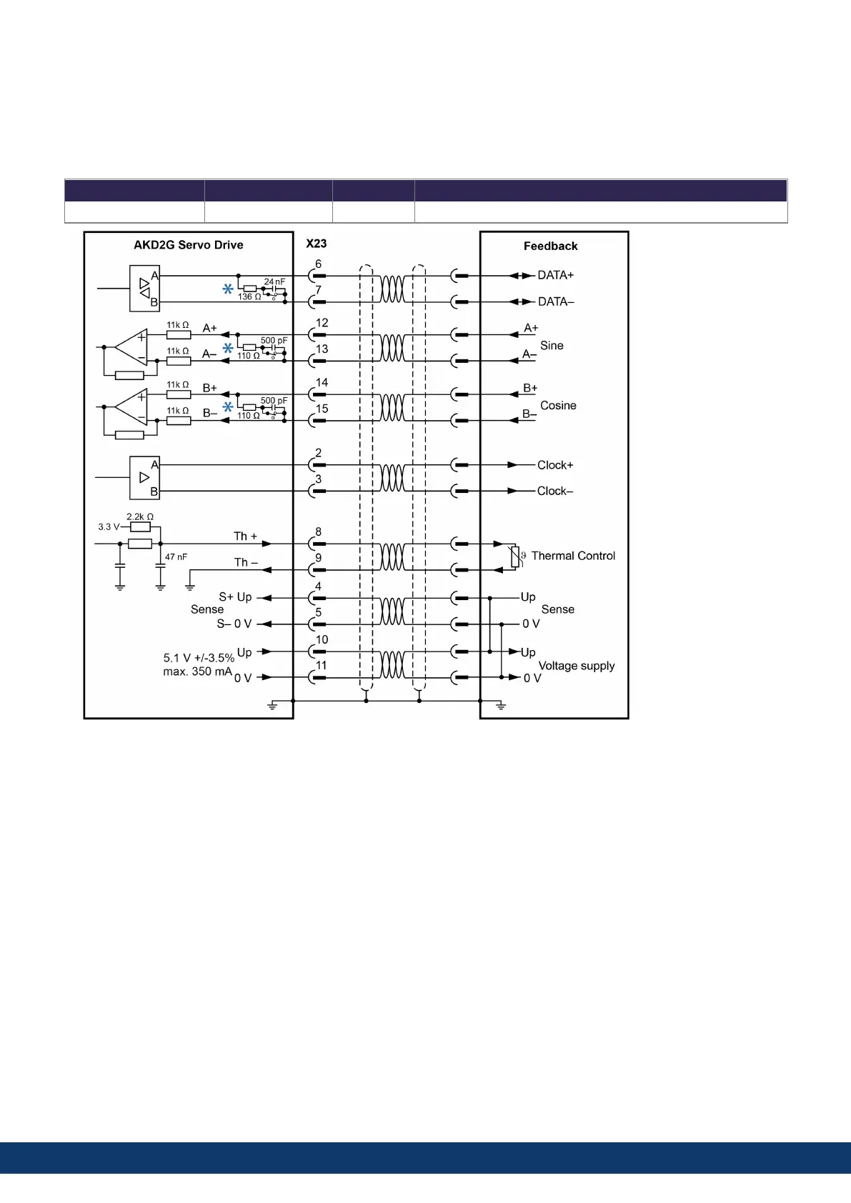
8.10.10.3 X23 BiSS (Mode B) Analog Feedback
The diagram below shows the wiring of a single-turn or multi-turn encoder with BiSS Mode B interface as a feedback
system. The thermal control in the motor is connected via the encoder cable and evaluated in the drive.
If cable lengths of more than 50m are planned, please consult customer support.
Type FBx.INDENTIFIED Up Frequency Limit
BiSS (Mode B) Analog 32 5.1 V ± 3.5% 1 MHz, 250 kHz for encoders that require termination resistors
*
DC terminated by default - DC switch closed.
114 Kollmorgen | kdn.kollmorgen.com | June, 2023

 Loading...


