AKD2G-S Installation Manual, Safety 1 | 8 Electrical Installation
8.10.10.7 X23 HIPERFACE Feedback
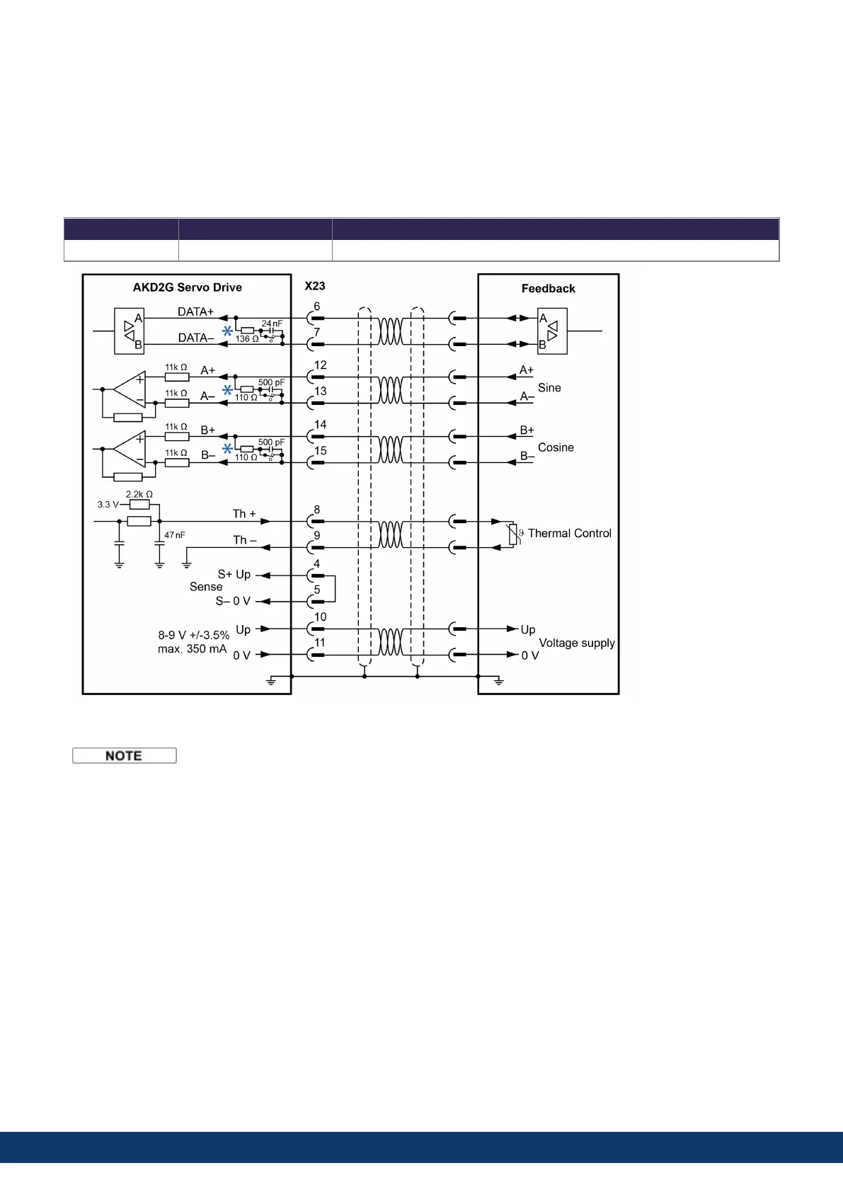
The diagram below shows the wiring of a single-turn or multi-turn sine-cosine encoder with Hiperface interface as a
feedback system.
The thermal control in the motor is connected via the encoder cable and evaluated in the drive. All signals are
connected using our pre-assembled encoder connection cable.
If cable lengths of more than 50 m are planned, please consult customer support.
Type FBx.INDENTIFIED Frequency Limit
HIPERFACE 33 1 MHz, 250 kHz for encoders that require termination resistors
*
DC terminated by default - DC switch closed.
Connecting pin 4 and 5 together causes Up to be 8 to 9V.
118 Kollmorgen | kdn.kollmorgen.com | June, 2023

 Loading...


