AKD2G-S Installation Manual, Safety 1 | 8 Electrical Installation
8.3 Wiring
Only professional staff who are qualified in electrical engineering are allowed to install the drive. Wires with
color green with one or more yellow stripes must not be used other than for protective earth (PE) wiring.
When installing or replacing cables, use only standardized components, which comply to the cable and
wire requirements (➜ # 55).
8.3.1 General
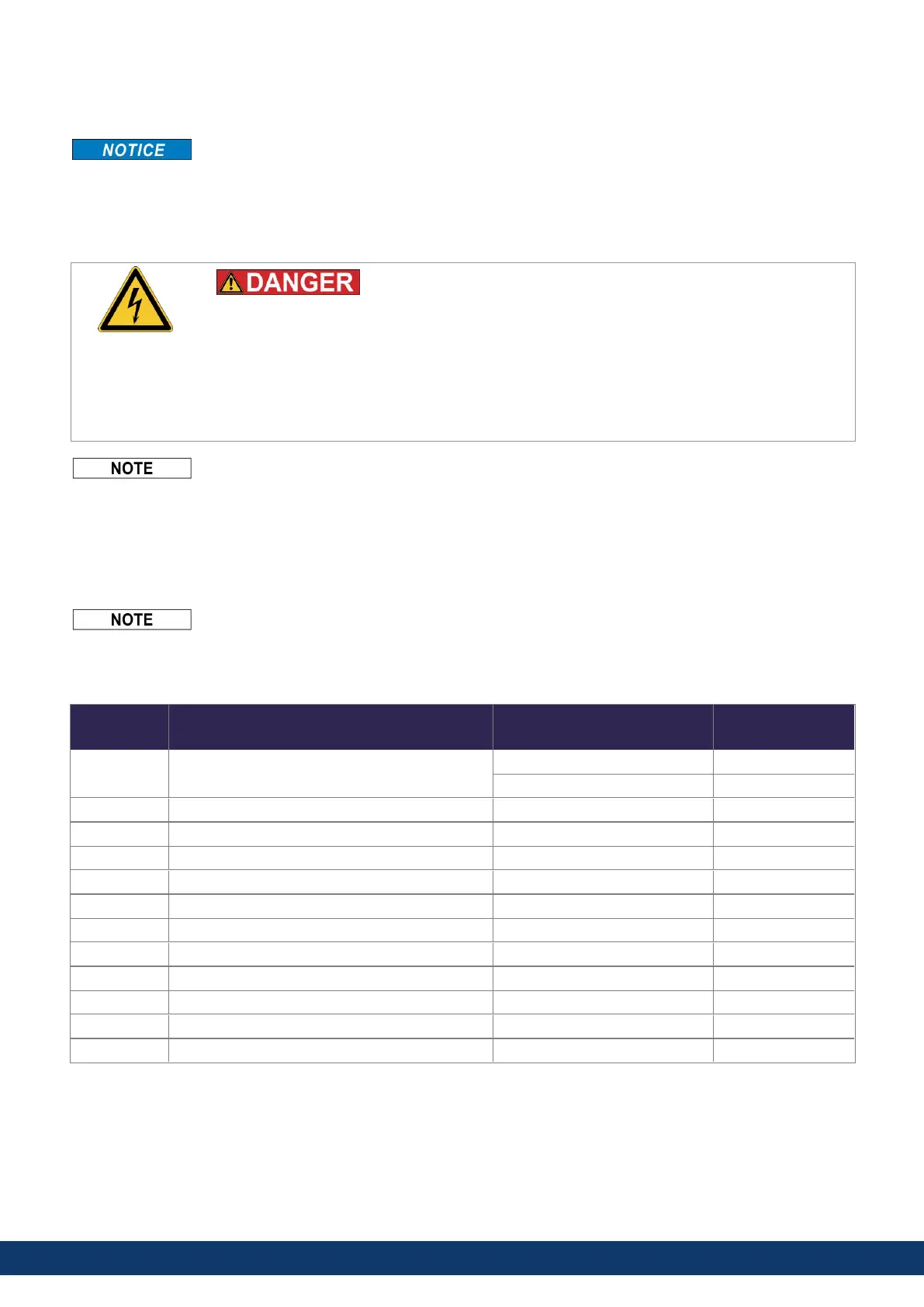
High Voltage up to 900 V!
There is a danger of serious personal injury or death by electrical shock or electrical arcing.
l
Only install and wire the equipment when it is not live, that is, when neither the electrical
supply nor the 24 V auxiliary voltage nor the supply voltages of any other connected
equipment is switched on.
l
Make sure that the cabinet is safely disconnected (for instance, with a lock-out and
warning signs). The individual voltages are switched on for the first time during setup.
The chassis ground symbol, which is used in all the wiring diagrams, indicates that you must take care to
provide an electrically conductive connection with the largest feasible surface area between the unit
indicated and the mounting plate in the control cabinet. This connection is for the effective grounding of HF
interference, and must not be confused with the PE-symbol (PE = protective earth, safety measure as per
IEC 60204).
8.3.2 Mating connectors
l
Connectors X1, X2, X4, X5, X10T, X21, X22 are spring clamp connectors.
l
X3/X3T connector with screw terminals, tightening torque 0.5...0.6 Nm (4.4...5.3 in-lbs).
l
X3A/X3B connector with screw terminals, tightening torque 2 Nm (18 in-lbs).
l
Connectors X4, X5, X22 and X23 are optional.
# Description Type Max. Cross
Section
X1/2 Motor, two wire feedback, holding brake Connector, 4 pol. power 10 mm², 8 awg
Connector, 4 pol. signal 0.5 mm², 21 awg
X3/X3T Mains power, regen resistor, DC-Bus Connector or T-type, 8 pol. 6 mm², 10 awg
X3A/X3B Mains power, regen resistor, DC-Bus Connector, 4 pol. power 6 mm², 10 awg
X4 Second brake Connector, 3 pol. 1.5 mm², 16 awg
X5 Second feedback, two wire Connector, 3 pol. 1.5 mm², 16 awg
X10T 24V power supply T-type connector , 2 pol. 2.5 mm², 14 awg
X11/12 EtherNet Fieldbus RJ45 0,5 mm², 21 awg
X13/14 CAN In/Out RJ25 0,5 mm², 21 awg
X20 Service Port RJ45 0,5 mm², 21 awg
X21 I/O control signals Connector, 2x11 pol. 1.5 mm², 16 awg
X22 I/O control signals Connector, 2x10 pol. 1.5 mm², 16 awg
X23 Conventional feedback models SubD 15pol. HD (female) 0,5 mm², 21 awg
54 Kollmorgen | kdn.kollmorgen.com | June, 2023

 Loading...


