8.5.5 Connector pinout
Information to wiring, mating connectors and cables (➜ # 54).
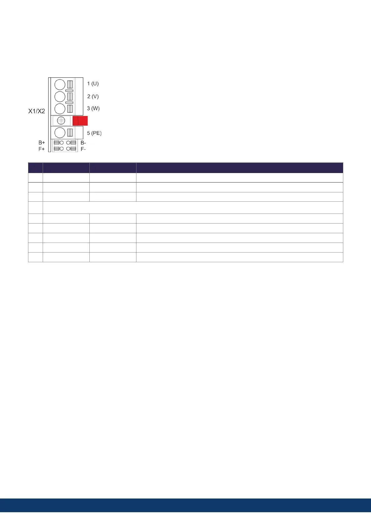
8.5.5.1 X1 and X2: Motor, Brake, Feedback 1
l
4 pin, pitch 7.62 mm plus 2x2 pin pitch 3.81 mm
l
Spring clamps
l
Locking screw, tightening torque 0.5 Nm (4.4 inlbs)
l
Motor power, Motor brake (X1: axis 1, X2: axis 2)
l
X1: Input for commutation feedback 1 (➜ # 106)
l
X2: Input for commutation feedback 2 (➜ # 106)
l
Wiring example:
l
DC Bus link (➜ # 92)
l
Motor single cable connection (➜ # 97)
l
Motor dual cable connection (➜ # 99)
Pin Label Signal
Description
1 U U Motor phase U
2 V V Motor phase V
3 W W Motor phase W
retention latch, shield screw
5 PE PE Protective earth
B+ B+ BR+ Motor holding brake +
B- B- BR- Motor holding brake -
F+ F+ COM+ SFD3 + or HIPERFACE DSL +
F- F- COM- SFD3 - or HIPERFACE DSL -
AKD2G-S Installation Manual, Safety 1
Kollmorgen | kdn.kollmorgen.com | June, 2023 69

 Loading...


