10.3.3.4 Timing
Example for axis 1.
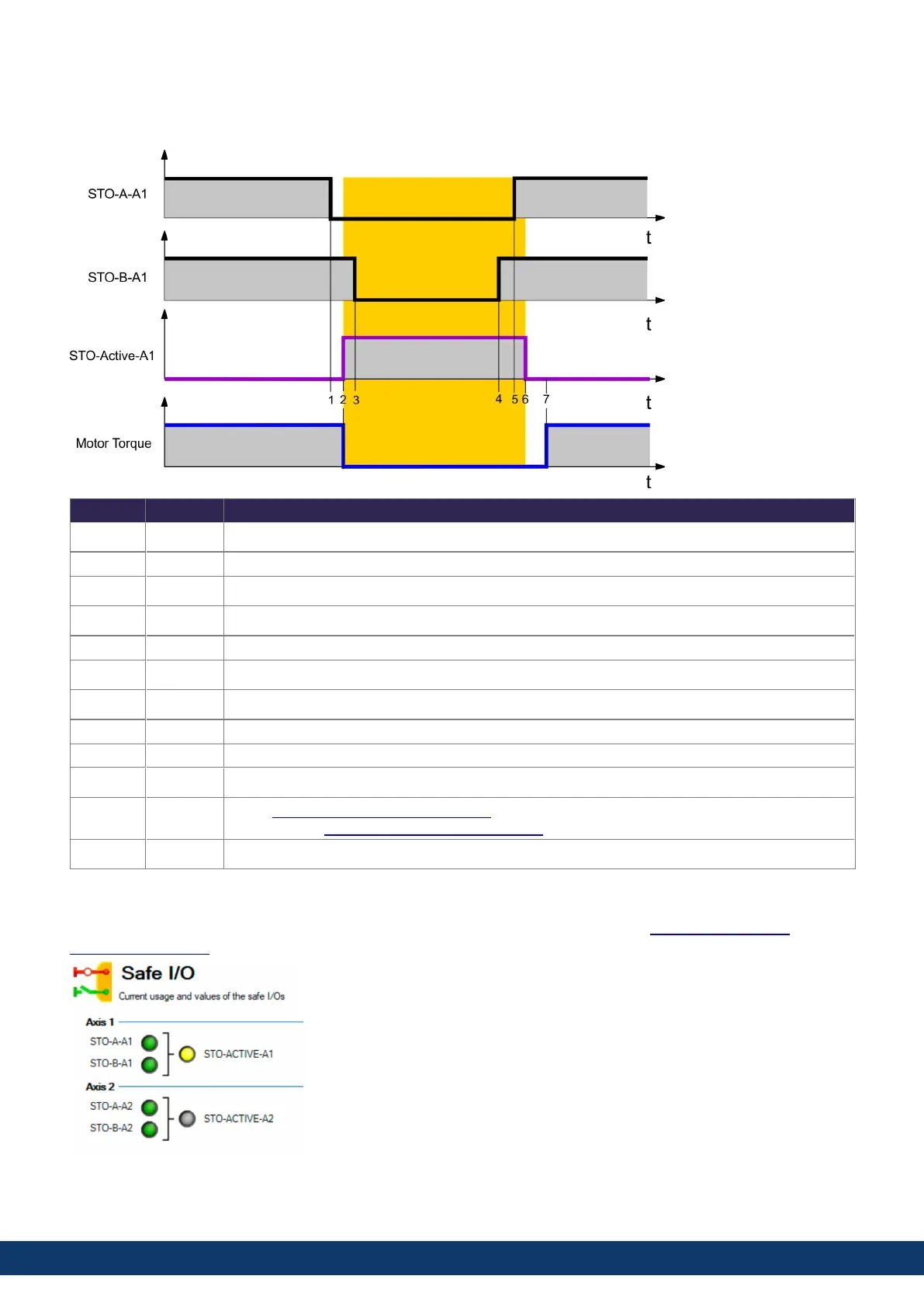
Timing max Remarks
t1 STO channel A enabled (0 V)
t1 to t2 2 ms STO enable delay (response time)
t2 STO active
t3 STO channel B enabled (0 V)
t1 to t3 100 ms accepted delay between dual channel edges
t4 STO channel B disabled (+24 V)
t5 STO channel A disabled (+24 V)
t4 to t5 100 ms accepted delay between dual channel edges
t5 to t6 2 ms STO release delay
t6 STO release
t6 to t7
Zero if AXIS#.SAFE.STO.REPORTFAULT=0
Until 'no fault' if AXIS#.SAFE.STO.REPORTFAULT=1
t7 Power section released.
10.3.3.5 Safety Diagnostic view in WorkBench
The WorkBench view "Safety Diagnostic" shows the current status on the safe inputs (AXIS#.SAFE.STO.A /
AXIS#.SAFE.STO.B) and the logical status of the STO function for every axis.
AKD2G-S Installation Manual, Safety 1
Kollmorgen | kdn.kollmorgen.com | S103, March 2023 187

 Loading...


