AKD2G-S Installation Manual, Safety 1 | 9 Setup
9.2 Guide to drive setup
Setup must be done in two major steps:
1. Drive setup (this section). This section presents an example to test the drive initially. If the drive (motor,
feedback, control circuits, I/Os) is well parameterized, then proceed with the
2. Functional Safety setup (➜ # 189) .
9.2.1 Initial Drive Test Procedure
9.2.1.1 Unpacking, mounting, and wiring the AKD2G
1. Unpack the drive and accessories.
2. Mount the drive.
3. Wire the drive or apply the minimum wiring for drive testing as described below.
4. Make sure you have on hand the following information about the drive components:
l
rated mains supply voltage
l
motor type (motor data, if the motor type is not listed in the motor database)
l
feedback unit built into the motor (type, poles/lines/protocol)
l
moment of inertia of the load
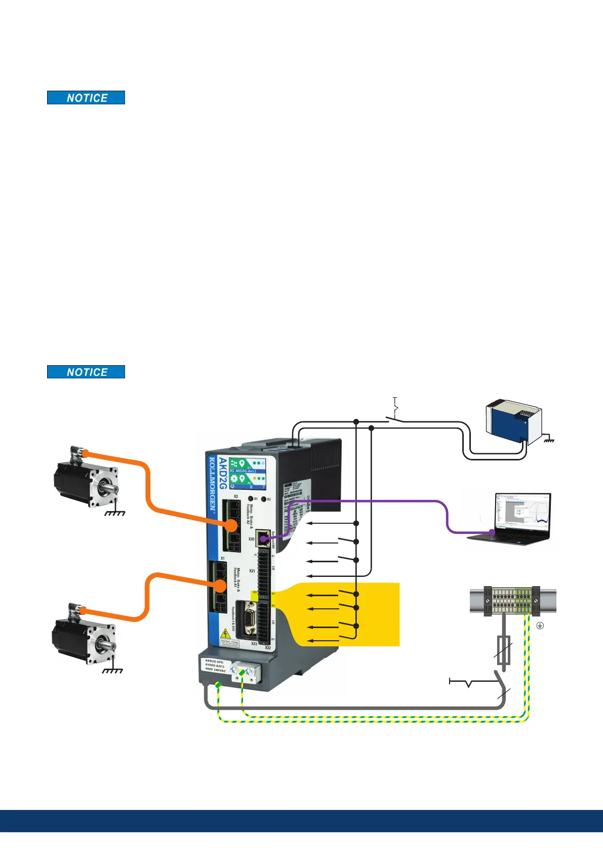
9.2.1.2 Minimum wiring for drive test without load, example
This wiring diagram based on default settings is for general illustration only and does not fulfill any
requirements for EMC, functional safety, or functionality of your application.
L1 L2 L3
24 VDC OUT
24V Supply
X10/1
X10/2
X21/A11
X21/B11
STO-A-A1
STO-B-A1
X22/A12
X22/B12
STO-A-A2
STO-B-A2
X21/B4
DGND
X21/B3
24V I/O
X21/A6
X21/A5
HW-Enable A1
HW-Enable A2
X20
3
3
Motor 1
Motor 2
Fuses
Mains
Power
Logic
Power
Power ON
+24V DC
24V ON
GND
164 Kollmorgen | kdn.kollmorgen.com | June, 2023

 Loading...


