2MN/2N1
1-5-63
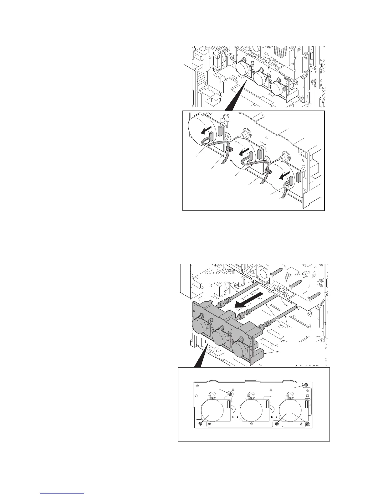
11. Release wire saddles.
30ppm model/35ppm model: 1
45ppm model/55ppm model: 2
12. Remove connectors.
30ppm model/35ppm model: 1
45ppm model/55ppm model: 3
Figure 1-5-97
13. Remove five screws and then remove
the drum drive unit MCY.
*: Do not have a shaft part alone when
you carry drum drive unit MCY. (Have
the housing.)
*: Put support on the tip of the shaft so
that the shaft may become the horizon-
tal when you put drum drive unit MCY
on the table etc.
14. Check or replace the drum drive unit K
and the drum drive unit MCY and refit
all the removed parts.
Figure 1-5-98
Connector
Connector
Connector
Wire saddle
Wire saddle
Screw
Screw
Screws
Screw
(Shaft portion)
Drum drive
unit MCY
(housing portion)
(Shaft portion)
 Loading...