General information
The Lexmark
TM
CS310 , CS410 , and CS510 models are color network printers in compact sizes. Some models have
internal duplex printing, USBA host ports for flash drives on the operator panel, and an optional 650-sheet Duo Drawer
with 550 sheets in the input tray and 100 sheets for the multipurpose feeder. The Lexmark 5027‑630 has a standard
650-sheet Duo Drawer and the option to add a 550-sheet tray, which brings the input for that model up to 1,451 sheets.
The Lexmark 5027‑610 comes with wireless network and duplex printing. All information in this service manual pertains
to all models unless explicitly noted.
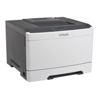
The printers are available in the following models:
Model Configurations Machine type / model
CS310n Ethernet network, DDR3 DIMM, Flash memory, optional
650‑sheet duo drawer with integrated multipurpose feeder
5027‑210
CS310dn Ethernet network, duplex, DDR3 DIMM, Flash memory,
optional 550‑sheet tray, optional 650‑sheet duo drawer
with integrated multipurpose feeder
5027‑230
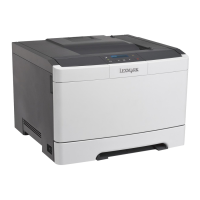
CS410n Ethernet network, USBA host port for flash drives, 2.4”
display and UICC card, standard 650‑sheet duo drawer with
integrated multipurpose feeder
5027‑410
CS410dn USBA host port for flash drive, duplex, Ethernet network,
2.4” display and UICC card, standard 650‑sheet duo drawer
with integrated multipurpose feeder
5027‑430
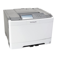
CS510de USBA host port for flash drive, duplex, 802.11n wireless
network, Ethernet network, hard disk option, UICC card,
4.3” display, standard 250‑sheet tray
5027‑630
CS510dte USBA host port for flash drive, duplex, 802.11n wireless
network, Ethernet network, hard disk option, UICC card,
4.3” display, standard 650‑sheet duo drawer with
integrated multipurpose feeder
5027‑630
C2132 USBA host port for flash drive, duplex, 802.11n wireless
network, Ethernet network, hard disk option, UICC card,
4.3” display, standard 250‑sheet tray
5027‑639
The diagnostic information in this manual leads you to the correct field replaceable unit (FRU) or part. Use the error
code charts, symptom index, and service checks to determine the symptom and then repair the failure. After you
complete the repair, perform tests as needed to verify the repair.
To begin diagnosing a problem, go to
“Diagnostic information” on page 33. See “Repair information” on page 197
for information about removing and reinstalling parts. See
“Parts catalog” on page 316 to help identify parts.
Media guidelines
• “Paper guidelines” on page 24
5027
General information
23