c Connect the cable to the tray present sensor.
d Replace the spring.
Paper pick motor drive assembly standard tray removal
1 Remove the waste toner bottle. See “Waste toner bottle removal” on page 250.
2 Remove the imaging unit. See “Imaging unit (IU) removal” on page 246.
3 Remove the left cover assembly. See “Left cover assembly removal” on page 219.
4 Remove the rear cover. See “Rear cover removal” on page 290.
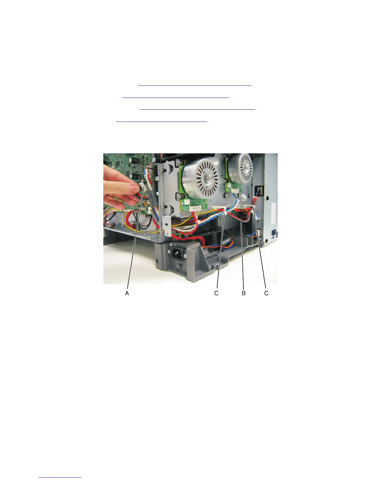
5 Disconnect the paper pick motor drive assembly cable connector (A) from JSP1 on the controller board.
6 Pull the cable (B) through the opening, and free the cables from their retainers (C) on the left.
7 Partially reinstall the rear cover to protect the controller board, and turn the printer so that the rear cover rests on
the table. The bottom should be facing you.
Warning—Potential Damage: For models with a wireless antenna, use supports to prevent the antenna from
taking the weight of the printer.
5027
Repair information
287