Direct Fuel Injection
Page 3B-80 90-8M0050731 MAY 2011
Description Nm lb‑in. lb‑ft
Nut securing air compressor 34 25
8. Tighten the two top screws (M10 x 25) securing the air compressor assembly to the cylinder block to the specified torque.
Description Nm lb‑in. lb‑ft
Screw (M10 x 25) (2)
First 1.5 13
Final 56 41.3
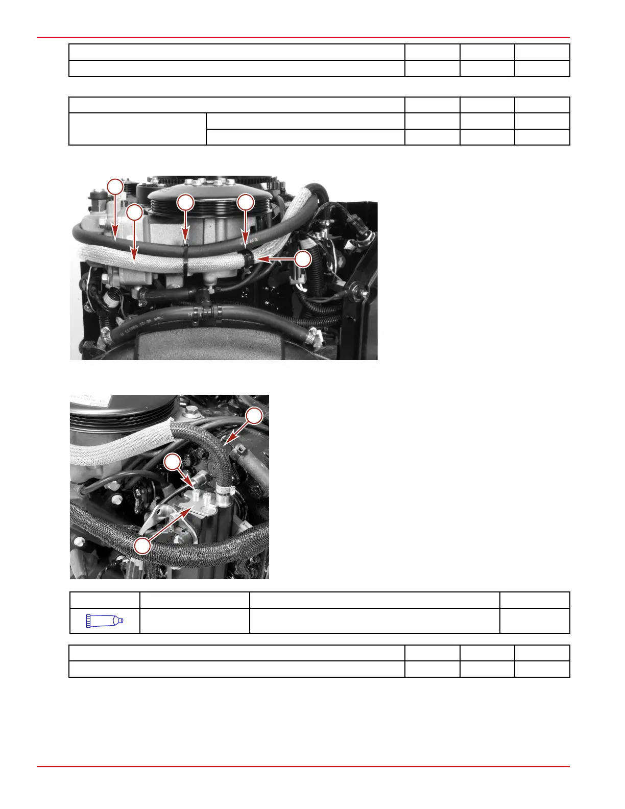
9. Secure the air compressor hose to the air compressor with a J‑clamp and cable tie. Secure the water hose and air compressor
hose to the air compressor with a cable tie.
a - Water hose
b - Air compressor to fuel rail hose
c - Cable tie
d - Plastic J‑clamp
10. Install two O‑rings onto the fuel rail air compressor hose fitting. Lubricate the O‑rings with 2‑cycle Premium Outboard Oil.
11. Install the fitting into the fuel rail and secure with a retainer and two screws. Tighten the screws to the specified torque.
a - Retainer
b - Screw (2)
c - Air compressor hose
Tube Ref No. Description Where Used Part No.
14
2-cycle Premium
Outboard Oil
O-rings on the fuel rail air compressor hose fitting 92-858021K01
Description Nm lb‑in. lb‑ft
Screw 8 71
12. Secure the water inlet hose to the air compressor with a cable tie.

 Loading...


