CHECKING CUTTING CONDITIONS [TEST CUT]
2-33
Checking the status of tools
Check the relation between the tools (th pen and the tangential cutter, and the pen and the crease roller) using the
TEST CUT function.
For this purpose, perform plotting first using the pen, then execute the test cut function using the tangential cutter or
the crease roller at the same position to check the relation between the tools.
The following describes how to correct problems on ten samples. The number of items required to be adjusted differs
with the samples. Determine the items to be adjusted using the samples as a guide. In these sample, the relation
between the pen and the tangential cutter is explained. In the case of the crease roller, read the following while replac-
ing the description “tangential cutter” with the “crease roller.”
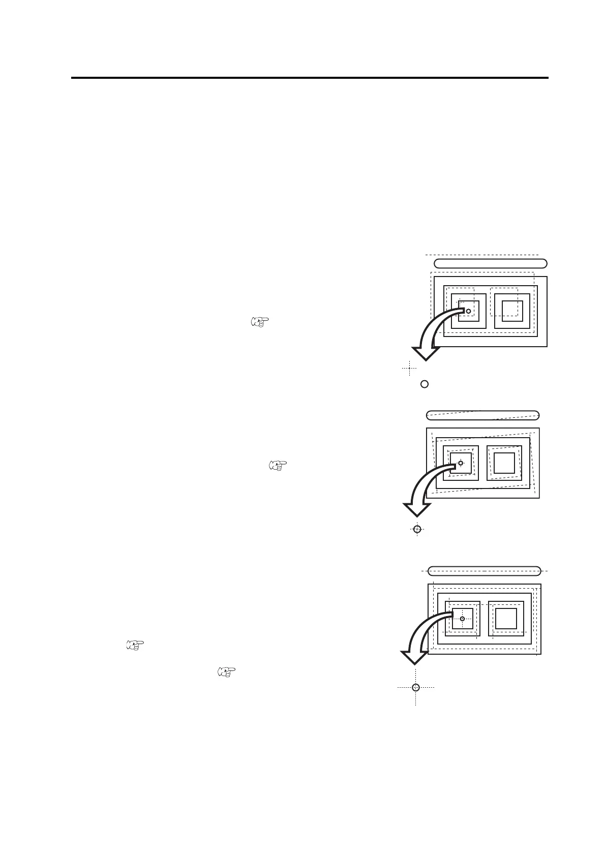
Sample A
The tangential cutter is out of the correct position regardless of
the proceeding direction.
Corrective measure
Perform the offset function contained in the cutter adjusting func-
tions of the tool adjusting functions.( P. 3-11)
Sample B
The cutter rotates clockwise (or counterclockwise).
Corrective measure
Conduct the q angle adjustment contained in the cutter adjusting
functions of the tool adjusting functions.( P. 3-8)
Sample C
The point from which the cutter starts is this side (or far side) of
the predetermined start position.
Corrective measure
Adjust the set value for the [START CORRECTION] in [CUT-
TING CONDITIONS] using the cutting condition setting func-
tions.( P. 2-23)
Adjust the pattern A for the “adjustment of the eccentricity” using
the tool adjusting functions.( P. 3-7)
 Loading...


