EasyManuals Logo

Minebea Intec X3 Process Indicator PR 5410 User Manual

Minebea Intec X3 Process Indicator PR 5410
340 pages
To Next Page IconTo Next Page
To Previous Page IconTo Previous Page
Page #84 background imageLoading...
Page #84 background image
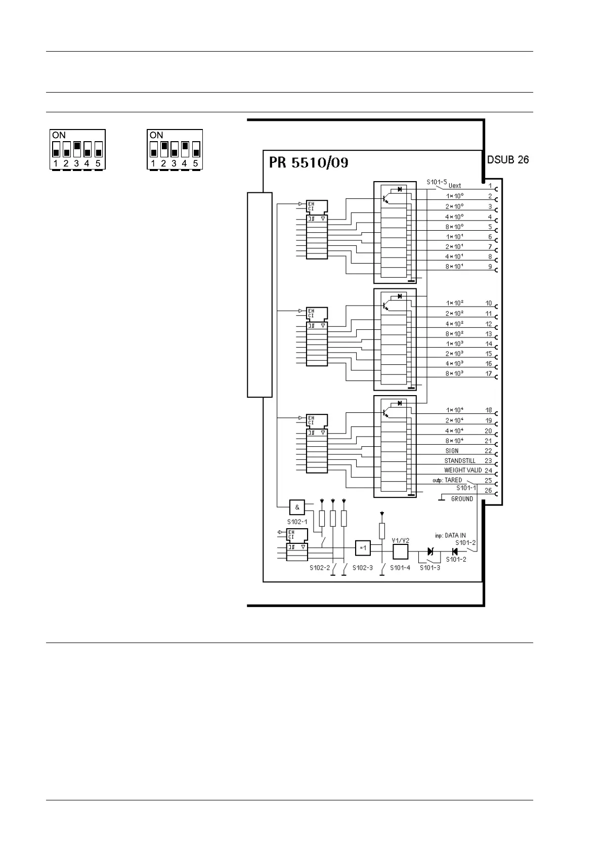
Switch for input PR 5510/09 block diagram
Factory setting:
S102
Factory setting:
S101
An external power supply is required: PIN 1 (Uext), reference po-
tential PIN 26 (GND)
4.6.6.1 Outputs
The outputs for PR 5510/09 (PIN 224) work as a reference potential and open collectors
with a shared ground.
A non-active output is highly resistant.
A voltage of 0.9 V is applied to an active output via GND.
The load to be connected is between the outputs (PIN 224, 25) and Uext (PIN 1).
X3 Process Indicator PR 5410 4 Device installation
Minebea Intec EN-82

Table of Contents

Questions and Answers:

Question and Answer IconNeed help?

Do you have a question about the Minebea Intec X3 Process Indicator PR 5410 and is the answer not in the manual?

Minebea Intec X3 Process Indicator PR 5410 Specifications

General IconGeneral
BrandMinebea Intec
ModelX3 Process Indicator PR 5410
CategoryTouch Panel
LanguageEnglish