Pin assignment Signal Color Description
3 -------------------- RxD/TxD-P (positive) ac-
cording to RS-485 speci-
cation
Red Send/receive data
Data core B/D (P)
4 if required RTS "Request To Send" (only when using a
repeater)
5 -------------------- DGND Insulated GND to RS-485 side
6 -------------------- VP Insulated power supply +5 V to
RS-485 side
7 Not connected
8 -------------------- RxD/TxD-N (negative) ac-
cording to RS-485 speci-
cation
Green Send/receive data
Data core A/D (N)
9 Not connected
Note:
You can only use plug connections with integrated terminating resistors.
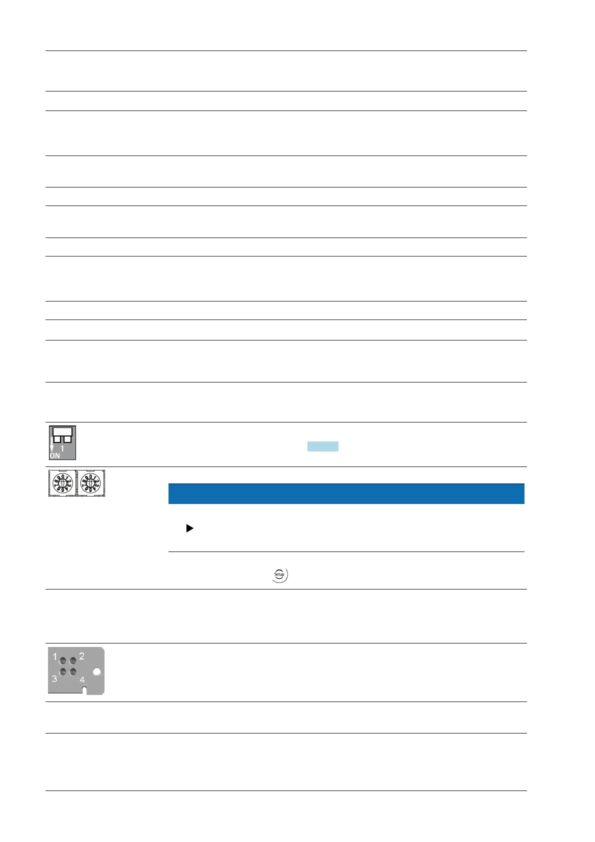
4.6.11.1 Controls on eldbus card
The terminating resistors can be switched on (ON) and o by pressing the bus ter-
mination switch ③; see Chapter 4.6.11.3.
NOTICE
The ④④ rotary switch settings will not be used.
Ensure that the three rotary switches for node address 199 are set to posi-
tion "0."
Settings are dened via - [Fieldbus parameter][Probus-DP].
4.6.11.2 LEDs in the module cover
The module cover can be found at the rear of the device.
⑥⑥
LED 1
No function
LED 2 LED 3 LED 4
O No diagnostics avai-
lable
X3 Process Indicator PR 5410 4 Device installation
Minebea Intec EN-96