- 124 -
Function
Code
Parameter Name Setting Range Default Unit Property
F5-25
X25 higher-voltage input
function selection
01–16 01 -
★
F5-26
X26 higher-voltage input
function selection
01–16 02 -
★
F5-27
X27 higher-voltage input
function selection
01–16 03 -
★
00: Invalid
Even if there is signal input to the terminal, the system has no response. You can allocate
this function to terminals that are not used to prevent mis-function.
01: Safety circuit signal
This terminal is used to detect the higher-voltage signal feedback of the safety circuit.
02: Door lock circuit 1 signal
This terminal is used to detect the higher-voltage signal feedback of the door lock circuit,
including the hall door circuit and car door lock circuit.
03: Door lock circuit 2 signal
This terminal is used to detect the higher-voltage signal feedback of the door lock circuit,
including the hall door circuit and car door lock circuit.
04–16: Reserved
Function Code Parameter Name Setting Range Default Unit Property
F5-28 Terminal state display 1 - - -
●
F5-29 Terminal state display 2 - - -
●
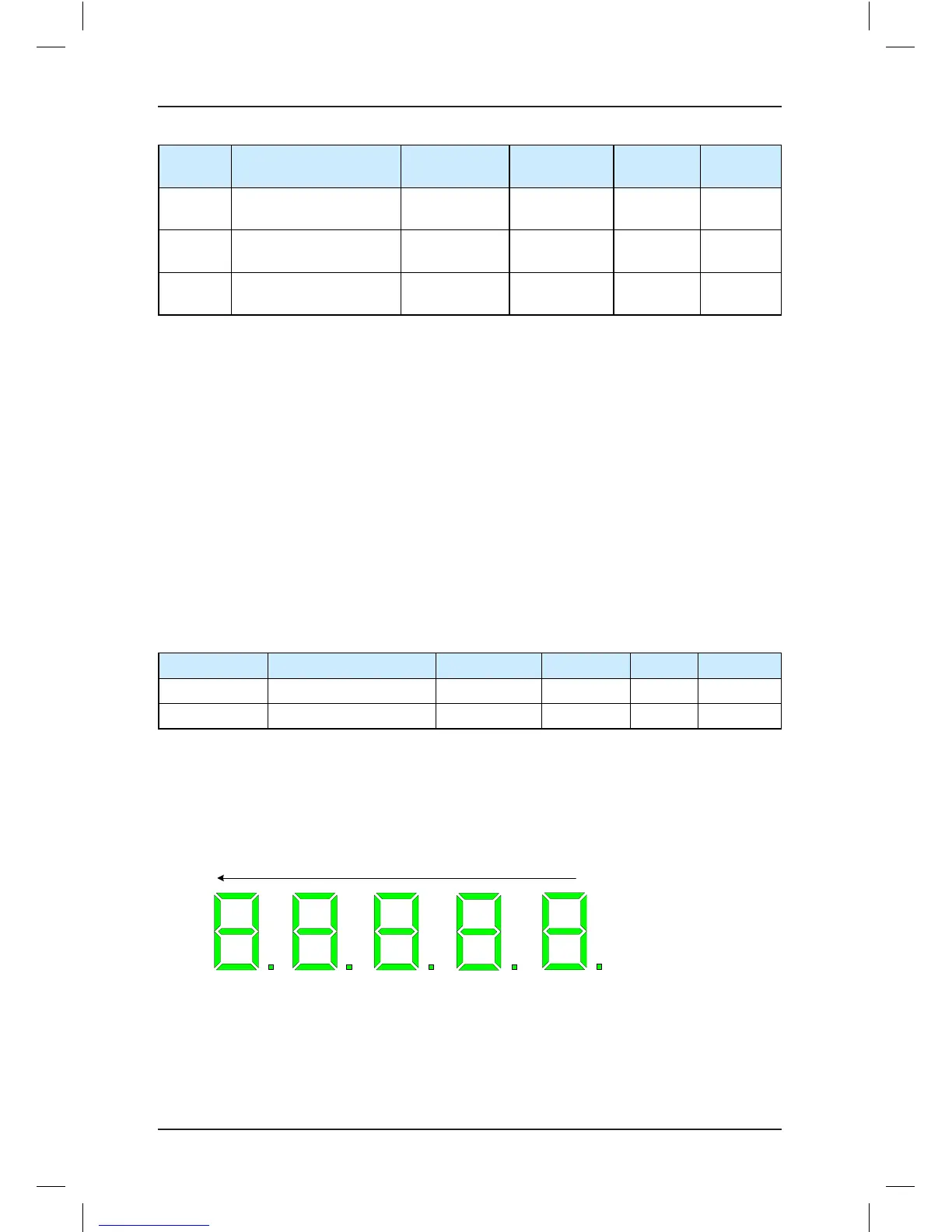
After you enter the F5-28 menu, the operation panel displays the state of all I/O terminals of
the system.
The LEDs are arranged as 5, 4, 3, 2, 1 from left to right.
Figure 7-4 I/O terminal state (F5-28)