NICE1000
new
User Manual Mechanical and Electrical Installation
- 43 -
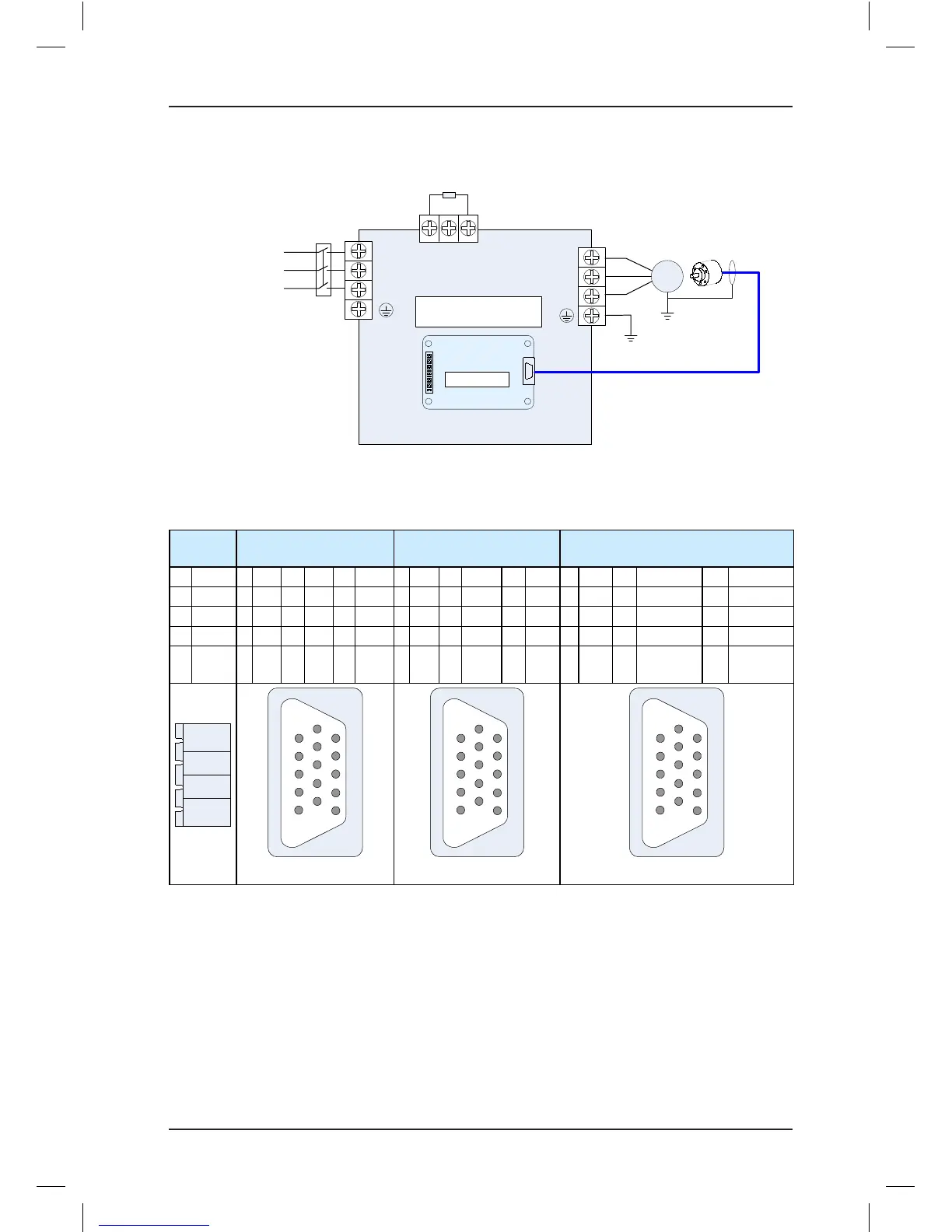
Figure 3-9 Wring between MCTC-PG-E and the controller
NICE1000
new
R
S
T
Three-phase AC
power supply
Safety
contactor
M
Braking resistor
+
–
PB
U
V
W
PG card
EncoderMotor
J1
CN1
MCTC-PG-E
The following table denes the CN1 terminals of different MCTC-PG card models.
Table 3-7 Denitions of the CN1 terminals of different MCTC-PG card models
MCTC-
PG-A2
MCTC-PG-D MCTC-PG-E MCTC-PG-F1
1 12V 1 A+ 6 N/A 11 W+ 1 B- 6 A- 11 C- 1 B- 6 A- 11 CLOCK-
2 PGM 2 A- 7 U+ 12 W- 2 N/A 7 COM 12 D+ 2 N/A 7 GND 12 DATA+
3 PGA 3 B+ 8 U- 13 VCC 3 Z+ 8 B+ 13 D- 3 N/A 8 B+ 13 DATA-
4 PGB 4 B- 9 V+ 14 COM 4 Z- 9 VCC 14 N/A 4 N/A 9 5V (Up) 14 N/A
5 N/A 10 V- 15 N/A 5 A+ 10 C+ 15 N/A 5 A+ 10 CLOCK+ 15
5V
(Sensor)
CN1
3. Precautions on connecting the MCTC-PG card
•
The cable connecting the MCTC-PG card and the encoder must be separated from the
cables of the control circuit and the power circuit. Parallel cabling in close distance is
forbidden.
•
The cable from the MCTC-PG card to the encoder must be a shielded cable. The shield
must be connected to the PE on the controller side. To minimize interference, single-end
grounding is suggested.
•
The cable from the MCTC-PG card to the encoder must run through the duct separately
and the metal shell is reliably grounded.