- 127 -
No. Segment Meaning of Segment ON
4
A Low 7-segment g display output active
B Up arrow display output active
C Down arrow output active
D Minus sign display output active
E Returning to base oor at re emergency output active
F Buzzer output active
G Overload output active
DP Arrival gong output active
5
A Full-load output active
B Inspection output active
C Fan/Lamp output 2 active
D Shorting door lock circuit contactor output active
E BCD/Gray code/7-segment high-bit output active
F Controller normal running output active
G Reserved
DP Reserved
Function Code Parameter Name Setting Range Default Unit Property
F5-30 Floor I/O terminal state display 1 - - -
●
F5-31 Floor I/O button state display 2 - - -
●
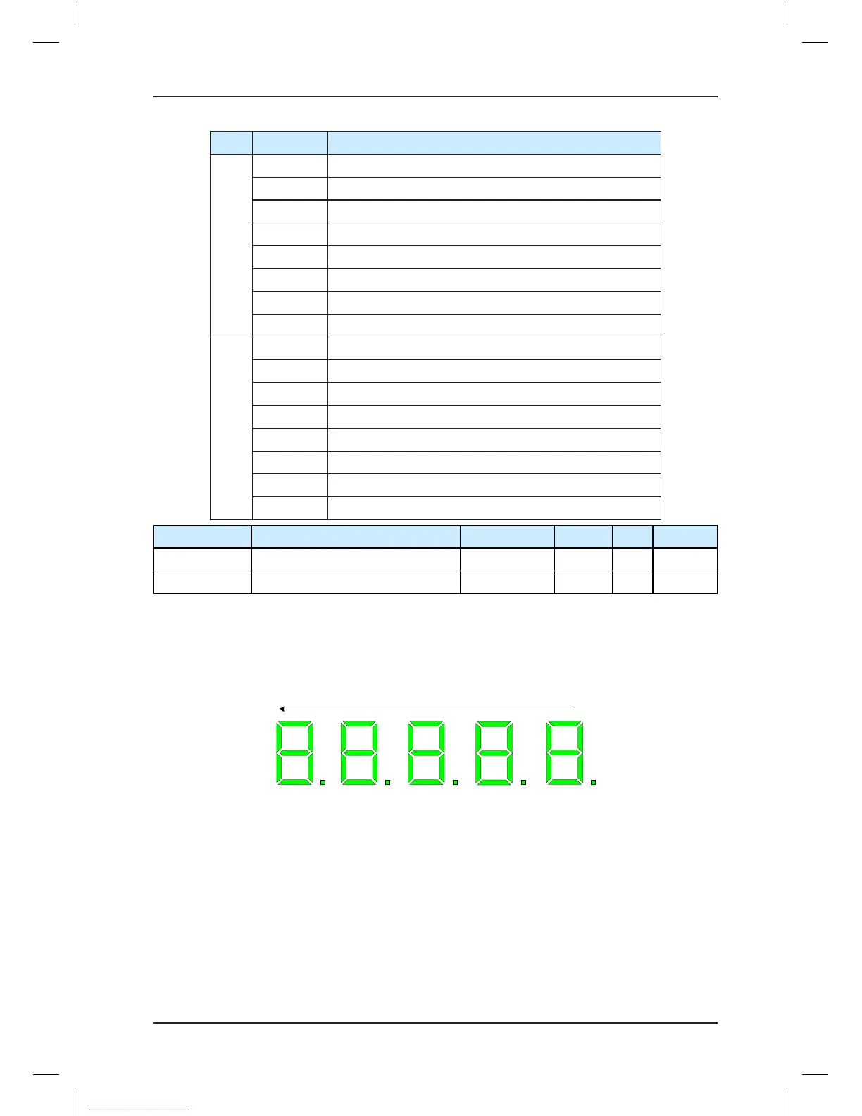
After you enter the F5-30 menu, the operation panel displays the state of all floor I/O
terminals of the system.
The LEDs are arranged as 5, 4, 3, 2, 1 from left to right.
Figure 7-5 Floor I/O terminal state (F5-30)