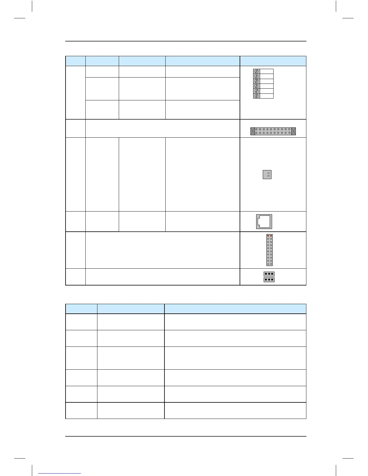
CAN+/-
CANbus
differential signal
CANbus communication
interface, used for parallel
control
GND Ground Must be grounded
CN5 Interface for extension board MCTC-KZ-D
J9/
J10
Factory reserved. Do not short them randomly. Otherwise,
the controller may not work properly.
Table 3-3 Description of indicators on the MCB
Mark Terminal Name Function Description
ER Fault indicator
When a fault occurs on the controller, this indicator is
ON (red).
OK Normal running indicator
When the controller is in normal running state, this
indicator is ON (green).
CAN
Parallel control
communication indicator
This indicator is steady ON (green) when
communication for parallel control is enabled, and blinks
when the running in parallel mode is normal.
L1 to L26 Button input indicator
This indicator is ON (green) when the button input is
active.
X1 to X27 Input signal indicator
This indicator is ON (green) when the external input is
active.
Y0 to Y22 Output signal indicator
This indicator is ON (green) when the system output is
active.