- 155 -
It displays the current communication quality of the system, as described in the following
table.
Table 7-16 Communication quality display
LED 5 LED 4 LED 3 LED 2 LED 1
SPI Communication
Quality
No Display
CAN2 Communication
Quality
No Display No Display
0 Good
-
0 Good
- -↓ ↑ ↓ ↑
9 Interrupted 9 Interrupted
0–9 indicates the communication quality. The greater the number is, the larger interference
the communication suffers and the poorer the communication quality is.
Function Code Parameter Name Setting Range Default Unit Property
FA-26 Input state 1 0–65535 0 -
●
FA-27 Input state 2 0–65535 0 -
●
FA-28 Input state 3 0–65535 0 -
●
FA-29 Input state 4 0–65535 0 -
●
FA-30 Input state 5 0–65535 0 -
●
FA-31 Output state 1 0–65535 0 -
●
FA-32 Output state 2 0–65535 0 -
●
FA-33 Output state 3 0–65535 0 -
●
FA-34 Floor I/O state 1 0–65535 0 -
●
FA-35 Floor I/O state 2 0–65535 0 -
●
FA-36 Floor I/O state 3 0–65535 0 -
●
FA-37 Floor I/O state 4 0–65535 0 -
●
FA-38 Floor I/O state 5 0–65535 0 -
●
FA-39 Floor I/O state 6 0–65535 0 -
●
FA-40 Floor I/O state 7 0–65535 0 -
●
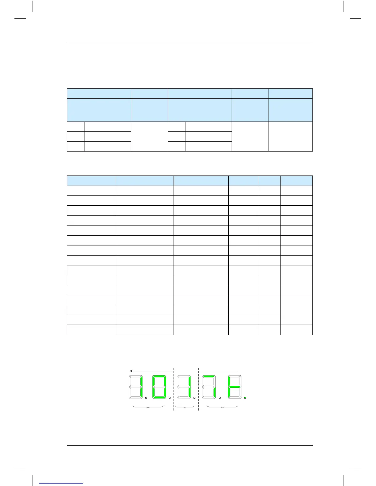
The following gure shows an example of the displayed input states.
Figure 7-9 Example of input state display