Mechanical and Electrical Installation NICE1000
new
User Manual
- 38 -
■
Description of Control Circuit Terminals
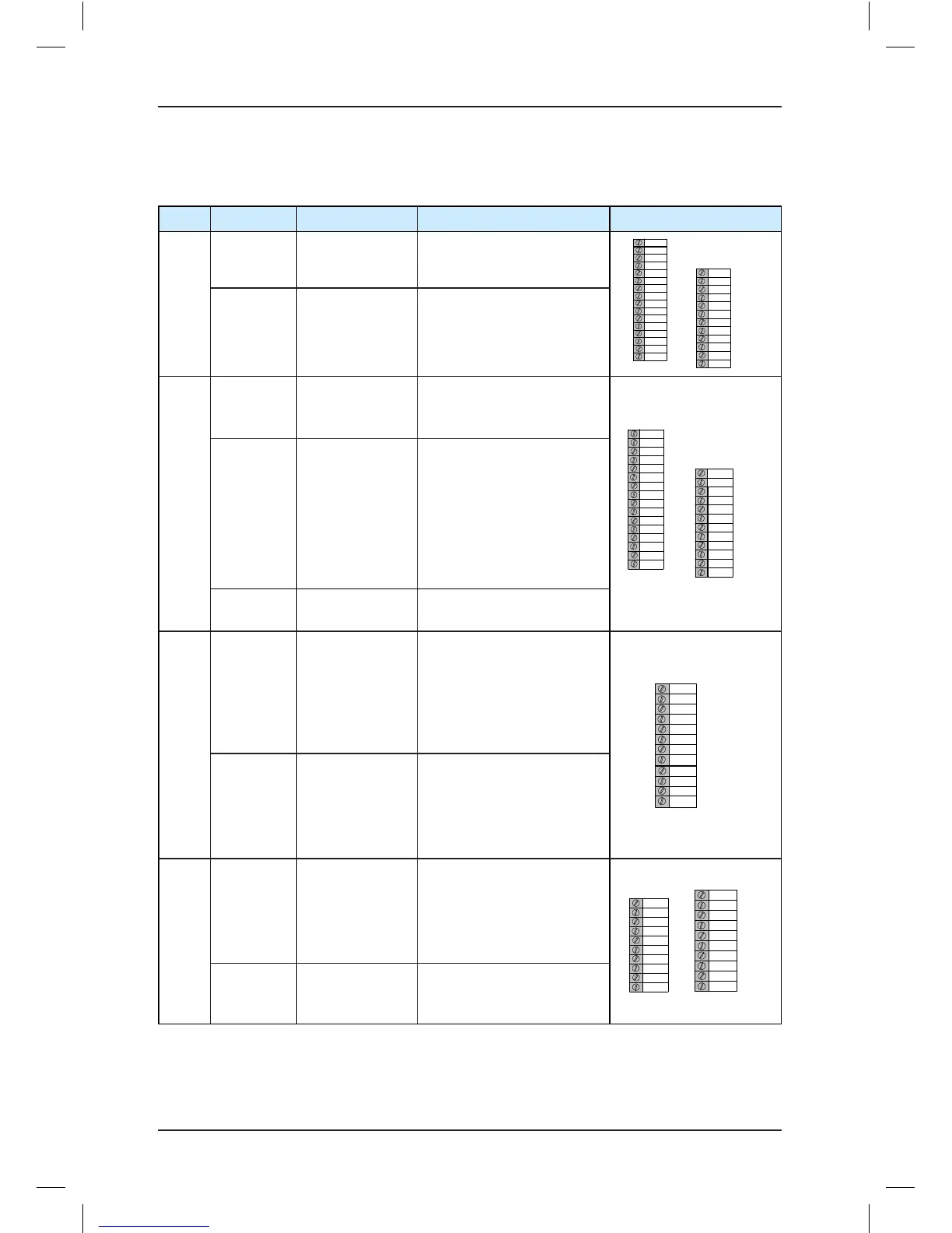
Table 3-2 Description of control circuit terminals
Mark Code Terminal Name Function Description Terminal Arrangement
CN2
CN4
24V/COM
External 24 VDC
power supply
24 VDC power supply for
the entire board
CN4
L1
L2
L3
L4
L5
L6
L7
L8
L9
L10
L11
L12
L13
L14
COM
24V
L17
L18
L
19
L20
L21
L22
L23
L24
L25
CN
2
L15
L16
L26
L1 to L26
Button function
selection
Button input and button
indicator output, 24 V power
for button illumination
CN1
CN6
24V/COM
External 24 VDC
power supply
24 VDC power supply for
the entire board
CN1
X1
X2
X3
X4
X5
X6
X7
X
8
X9
X10
X11
X12
X13
X14
COM
24V
X17
X18
X19
X20
X21
X22
X23
X24
AI-M
CN
6
X15
X16
AI
X1 to X24 DI
Input voltage range: 10–30
VDC
Input impedance: 4.7 kΩ
Optocoupler isolation
Input current limit: 5 mA
Functions set in F5-01 to
F5-24
AI-M/AI AI
Used for the analog load cell
device
CN7
X25 to X27/
XCM
Higher-voltage
detection
terminal
Input voltage range: 110
VAC±15%
110 VDC±20% for safety
circuit and door lock circuit,
function set in F5-25 to
F5-27
Y1
M1
Y2
M2
Y3
M3
Y0
M
0
CN7
XCM
X
25
X26
X27
Y0/M0 to
Y3/M3
Relay output
Normally-open (NO),
maximum current and
voltage rating: 5 A, 250 VAC
Function set in F7-00 to
F7-03
CN8
CN9
Y6 to Y22 Relay output
NO, maximum current and
voltage rating: 5 A, 250 VAC
or 5 A, 30 DC
Function set in F7-06 to
F7-22
Y6
Y7
Y8
Y9
YM1
Y10
Y11
Y12
Y13
Y14
CN8
Y15
Y16
YM2
Y17
Y18
Y19
Y20
Y21
Y22
YM3
CN9
YM1 to
YM3
COM for relay
output
YM1 is COM for Y6 to Y9;
YM2 is COM for Y10 to Y16;
YM3 is COM for Y17 to Y22.