In the formula,
"
L
"
indicates the slow-down distance,
"
V
"
indicates the F0-04 (Rated elevator
speed), and
"
F3-08
"
indicates the special deceleration rate.
The default value of F3-08 (Special deceleration rate) is 0.5 m/s
2
. The slow-down distances
calculated based on different rated elevator speeds are listed in the following table:
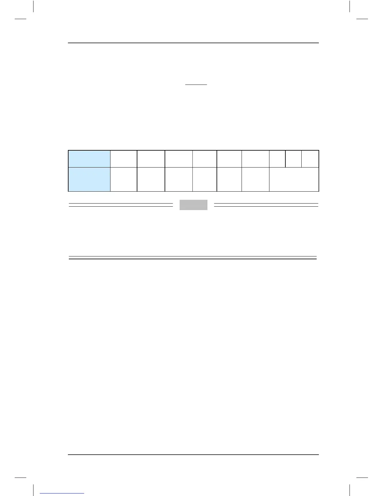
Table 3-11 Slow-down distances based on different rated elevator speeds
Rated Elevator
Speed (m/s)
0.25 0.4 0.5 0.63 0.75 1.0 1.5 1.6 1.75
Distance of
Slow-down
Switch (m)
0.3–0.4 0.5–0.6 0.6–0.8 0.8–1.0 0.9–1.2 1.2–1.5 1.8–2.5
•
The slow-down switch supports the terminal oor reset function. It must be installed between
the leveling plates of the terminal oor and the secondary terminal oor.
•
If the distance between these two oors is small and the installation distance of the slow-down
switch is outside the installation range of these two oors, enable the super short function by
setting Bit14 or Bit15 of F6-07.
3.6.3 Installation of Limit Switches
The up limit switch and down limit switch protect the elevator from over travel top/bottom
terminal when the elevator does not stop at the leveling position of the terminal oor.
•
The up limit switch needs to be installed 30−50 mm away from the top leveling position.
The limit switch acts when the car continues to run upward 30−50 mm from the top
leveling position.
•
The down limit switch needs to be installed 30−50 mm away from the bottom leveling
position. The limit switch acts when the car continues to run downward 30−50 mm from
the bottom leveling position.
3.6.4 Installation of Final Limit Switches
The nal limit switch is to protect the elevator from over travel top/bottom terminal when the
elevator does not stop completely upon passing the up/down limit switch.
•
The up nal limit switch is mounted above the up limit switch. It is usually 150 mm away
from the top leveling position.
•
The down nal limit switch is mounted below the down limit switch. It is usually 150 mm
away from the bottom leveling position.