EasyManuals Logo

Monarch NICE1000 User Manual

Monarch NICE1000
205 pages
To Next Page IconTo Next Page
To Previous Page IconTo Previous Page
Page #48 background imageLoading...
Page #48 background image
NICE1000
new
User Manual Mechanical and Electrical Installation
- 47 -
Figure 3-11 Arrangement of shaft position signals
Leveling plate
(floor N)
L
80 D 200 mm
150 mm
L >
2 x F3-08
Top leveling
position
D
L
150 mm
Up final limit
switch
Up limit
switch
30-50 mm
(V: Rated
elevator speed)
Up slow-down switch
Down slow-down switch
Bottom leveling
position
Down limit
switch
Down final
limit switch
3050 mm
L >
2 x F3-08
(V: Rated
elevator speed)
3.6.1 Installation of Leveling Signals
Leveling signals comprise the leveling switch and leveling plate and are directly connected
to the input terminal of the controller. It is used to enable the car to land at each floor
accurately.
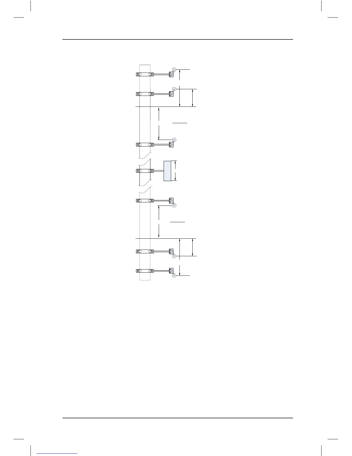
The leveling switches are generally installed on the top of the car. The NICE1000new
system supports a maximum of three leveling switches; by default, a leveling switch is used.
The leveling plate is installed on the guide rail in the shaft. A leveling plate needs to be
installed at each oor. Ensure that leveling plates at all oors are mounted with the same
depth and verticality.
The following gure shows the installation of leveling signals

Table of Contents

Questions and Answers:

Question and Answer IconNeed help?

Do you have a question about the Monarch NICE1000 and is the answer not in the manual?

Monarch NICE1000 Specifications

General IconGeneral
BrandMonarch
ModelNICE1000
CategoryController
LanguageEnglish

Related product manuals