- 126 -
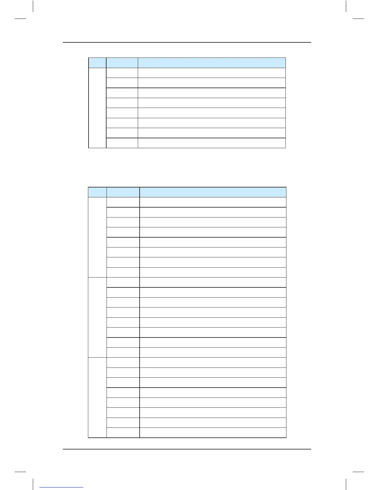
No. Segment Meaning of Segment ON
5
A Door 2 selection signal active
B UPS input signal active
C Door open button active
D Door close button active
E Door lock circuit 1 signal active
F Door lock circuit 2 signal active
G Half-load signal active
DP Reserved
The following table describes the meaning of the LED segments indicating the I/O terminal
state in F5-29.
Table 7-3 Meaning of the LED segments for F5-29
No. Segment Meaning of Segment ON
1
A Invalid
B Safety circuit signal active
C Door lock circuit 1 signal active
D Door lock circuit 2 signal active
E Reserved
F Reserved
G Reserved
DP Reserved
2
A Y0 output active
B RUN contactor output active
C Brake contactor output active
D Higher-voltage startup of brake active
E Fan/Lamp output active
F Shorting PMSM stator contactor output active
G Door 1 open output active
DP Door 1 close output active
3
A Door 2 open output active
B Door 2 close output active
C Low 7-segment a display output active
D Low 7-segment b display output active
E Low 7-segment c display output active
F Low 7-segment d display output active
G Low 7-segment e display output active
DP Low 7-segment f display output active