Network Setup 4-15
3. Click the Add button.
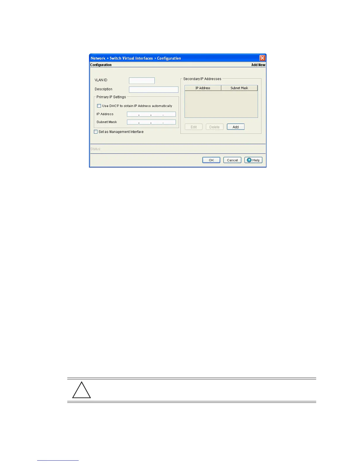
4. Enter the VLAN ID for the switch virtual interface.
5. Provide a Description for the VLAN, representative of the VLAN’s intended operation within the switch
managed network.
6. The Primary IP Settings field consists of the following:
a. Select Use DHCP to obtain IP Address automatically to allow DHCP to provide the IP address
for the virtual interface. Selecting this option disables the IP address field.
b. Enter the IP Address for the VLAN associated virtual interface.
c. Enter the Subnet Mask for the IP address.
7. Select the Set as Management Interface checkbox to enable any host displayed in this VLAN to
configure the switch.
8. Use the Secondary IP Addresses field to define additional IP addresses to associate with VLAN IDs.
The address provided in this field is used if the primary IP address is unreachable.
Select the Add button (within the Secondary IP Addresses field) to define additional addresses from
a sub screen. Choose an existing secondary address and select Edit or Delete to revise or remove a
secondary address.
9. Refer to the Status field for the current state of the requests made from applet. This field displays error
messages if something goes wrong in the transaction between the applet and the switch.
10.Click OK to use the changes to the running configuration and close the dialog.
11.Click Cancel to close the dialog without committing updates to the running configuration.
4.4.1.2 Modifying a Virtual Interface
To modify an existing virtual interface.
1. Select Network > Switch Virtual Interface from the main tree menu.
CAUTION: When changing from a default DHCP address to a fixed IP address, set a static
route first. This is critical when the switch is being accessed from a subnet not directly
connected to the switch and the default route was set from DHCP.
 Loading...