Setting up Compax3
C3I10T10
192-120100 N16 C3I10T10 - December 2010
Resetting channel CH 1..4: All channel settings are deleted.
Please note: Channels can only be filled with sources one after the other. It is, for
example, not possible to start a measurement which has only a signal source for
channel 2!
Select channel color:Here you can change the color of the channel.
Show/hide channel:Hide/show display of the channel.
Change logic display mask:Mask bits in logic display.
Autoscale:Calculating YDIV and offset: The program calculates the best settings
for YDIV and channel offset in order to display the complete signal values
optimally.
Define source: Draw the desired status object with the mouse (drag & drop) from
the "Status value" window (right at the bottom) into this area.
Multiple oscilloscope in Compax3M: select device in addition to the object.
3: Set signal source with object name, number and if necessary unit
4: Set Channel offset to 0
DC:Display of the measurement values with constant component
5: Select channel display (GND, DC, AC, DIG)
AC:Display of the measurement values without constant component
DIG:Display of the individual bits of an INT signal source.
The displayed bits can be defined via the logic display mask.
GND:A straight line is drawn on the zero line.
Change of the Y amplification YDIV in the stages 1, 2, 5 over all decades.
Arrow upwards increases YDIV, arrow downwards diminishes YDIV.
The standard value is 1 per DIV.
The measurement value of the channel at the cursor cross is displayed.
6: Set Y-amplification (YDIV)
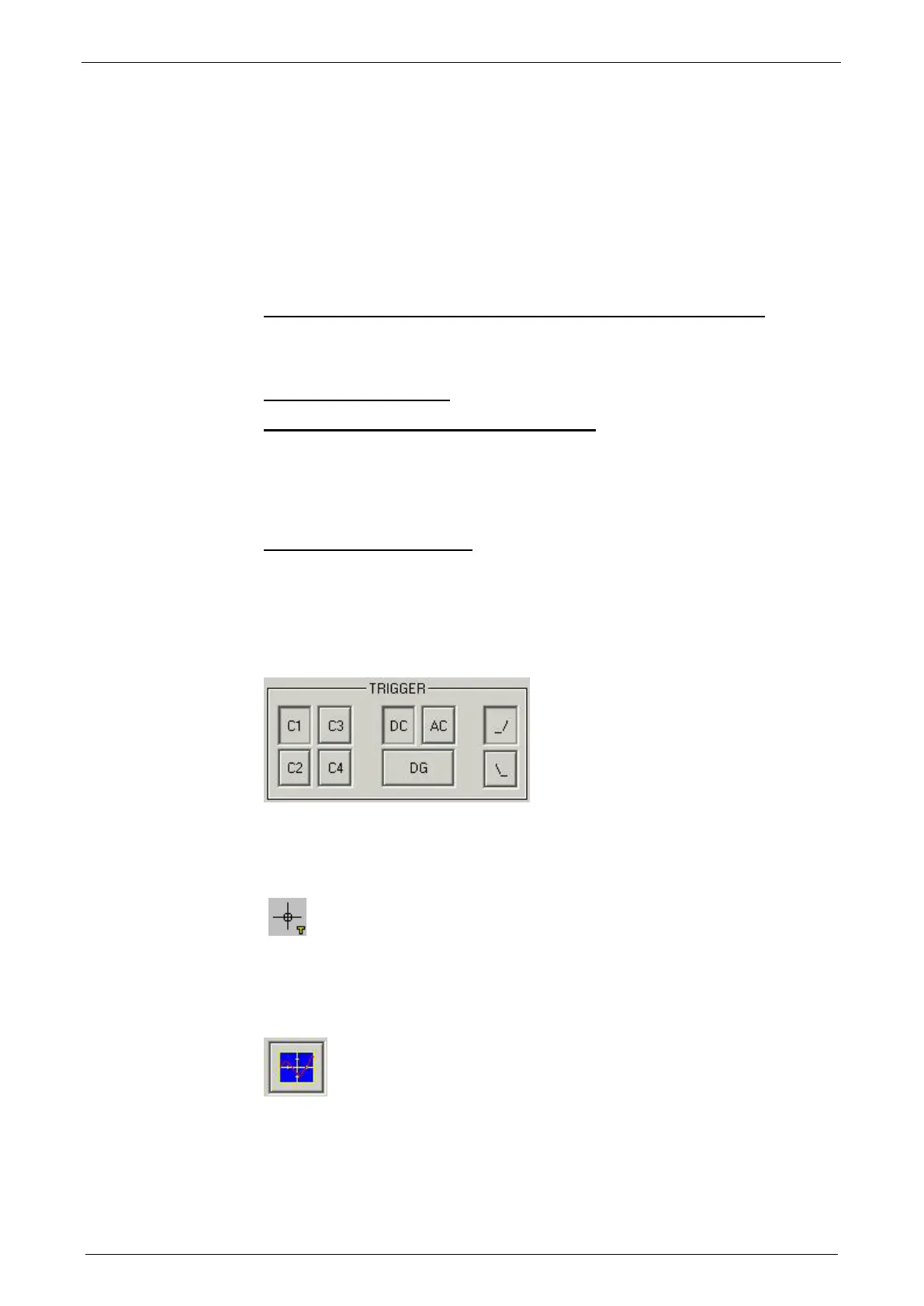
Trigger settings
Select trigger channel: Buttons C1, C2, C3, C4
Select trigger mode: DC, AC, DG
Selecting the trigger edge: Rising_/ or falling \\_.
The pretrigger as well as the trigger level are set by clicking on the trigger cursor
(
) directly in the OSCI display.
Special functions
Menu with special oscilloscope functions such as memorizing or loading settings.
 Loading...


