2 Basic repair procedures Chapter E: Basic repair procedures
132 Planmeca PlanMill 40 Technical manual
Figure 128: Bellows assembly removed
11. Use the small flat screwdriver to remove the (2) retaining screws and disconnect the
tool changer electrical connector from the rear of the tool changer assembly.
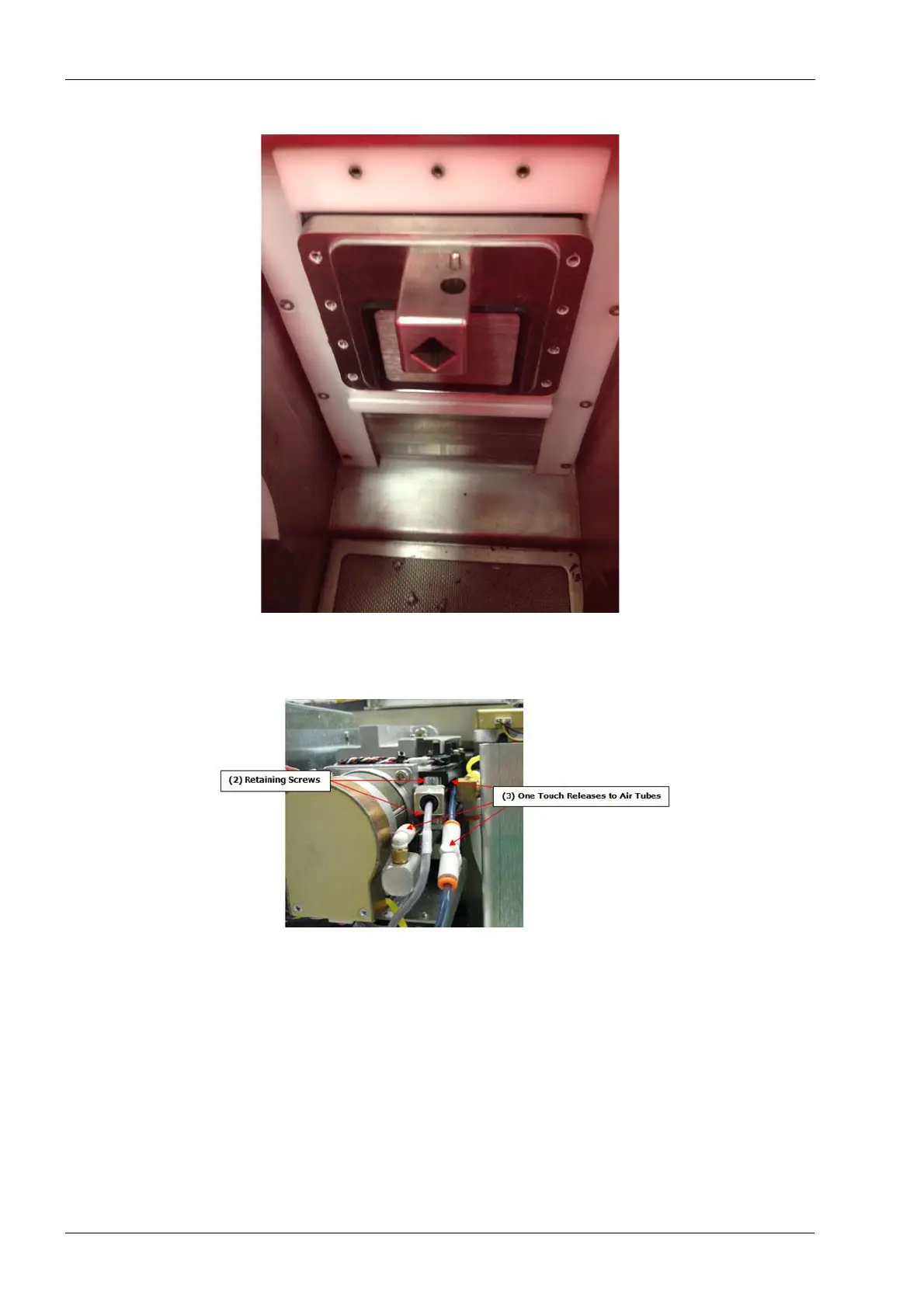
Figure 129: Disconnect cable and tubing
12. Disconnect the (3) air hoses from the tool changer, two from the air cylinder and one
from the purge orientation sensor.
Removing the front air cylinder tubing is possible using a small flat screw driver to depress
the one touch ring on the fitting to release the tubing.
13. Extend the Y-axis forward to allow access to the front mounting screws
Remember to never put pressure on the back face of the servo motor, this cover is thin
sheet metal and can bend, damaging the encoder.