Chapter E: Basic repair procedures 2 Basic repair procedures
Technical manual Planmeca PlanMill 40 133
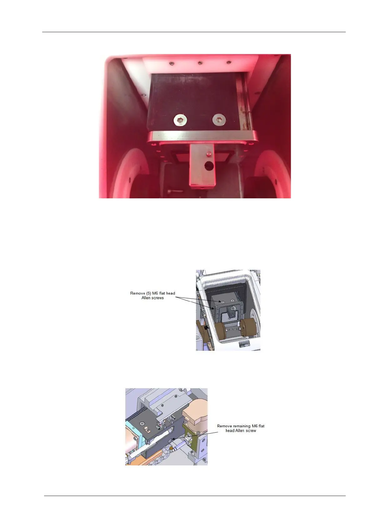
Figure 130: Correct position for tool changer removal
14. Remove the (5) M6 flat head Allen screws securing the front of the tool changer
assembly and remove the screws.
The (3) screws on the left side are best removed using the stubby style 4 mm Allen key due
to the tight space.
Figure 131: Removing screws securing front of tool changer assembly
15. Locate and remove the remaining M6 flat head Allen screw on the lower left side of
the Y-axis tube about 2/3 back, remove this screw.
Figure 132: Remove M6 llat head allen screw