2 Basic repair procedures Chapter E: Basic repair procedures
134 Planmeca PlanMill 40 Technical manual
Vertical adjustment of the Z-axis as well as fore/aft adjustment of the Y-axis will make
accessing this screw much easier.
16. Adjust so the Y-axis is fully back (retracted) and the Z-axis is fully up.
17. Slide the tool changer assembly forward. It will be necessary to rotate the tool
changer assembly counter clockwise 45 degrees or so to clear internal components,
allowing complete removal.
The rear section of the tool changer air cylinder can easily hang on the servo motor flange
and restrict removal, simply rotate the end of the air cylinder free of the flange and remove.
18. Inspect the internals of the Y-axis tube, wiping clean if necessary.
Install
1. Adjust so the Y-axis is fully back (retracted) and the Z-axis is fully up. Lock the Z-axis
in position using the locking procedure described previously.
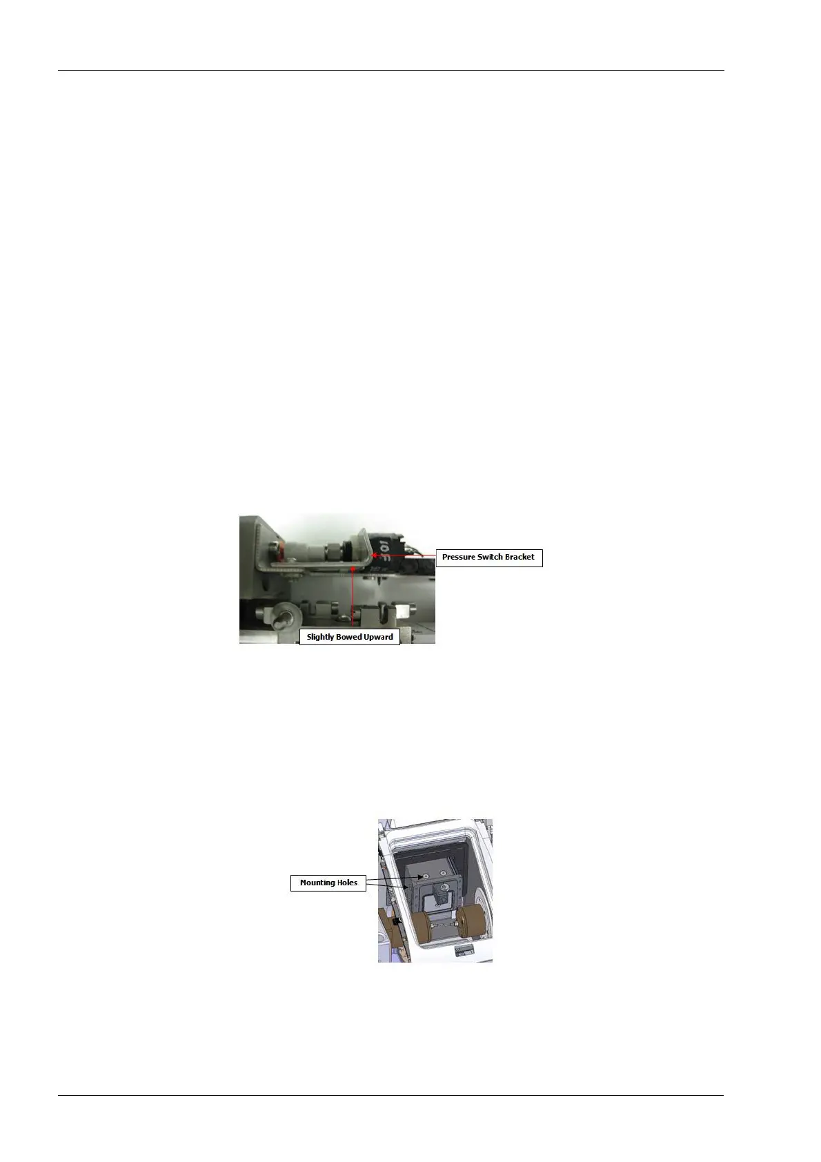
A very slight bend to the bracket will ensure clearance during operation.
Figure 133: Pressure swich bracket
2. Guide the tool changer into the Y-axis tube.
Position the tool changer assembly such that the back of the air cylinder and electrical
connector are inserted into the front of the Y-axis tube. You will need to rotate the assembly
approximately 45 degrees counter clockwise during the initial insertion process until the
tool changer is partially inserted at which time it can be rotated back to its normal position.
Figure 134: Installing screws securing front of tool changer assembly
3. Fully insert the tool changer assembly until all (6) mounting holes align with the Y-axis
tube.