Chapter E: Basic repair procedures 2 Basic repair procedures
Technical manual Planmeca PlanMill 40 135
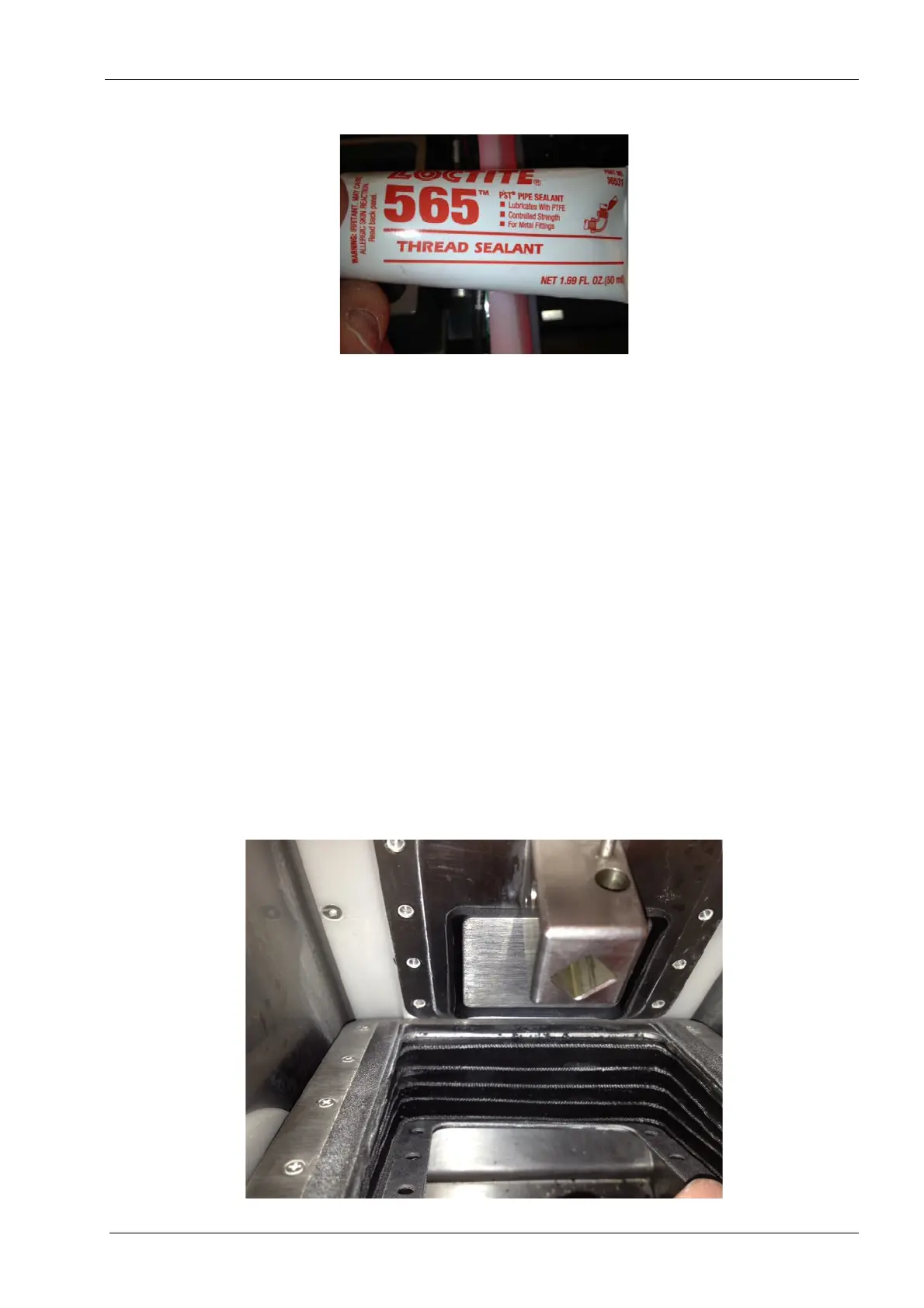
Figure 135: Thread sealant
4. Apply thread sealant to the (6) M6 flat screws Allen screws that secure the tool
changer assembly and install into assembly.
The three M6 screws on the left side can best be reached using the 4 mm stubby Allen key.
The 6th M6 screw can be found on Y-axis tube about 2/3 of the way back. Torque the
screws to 9.0 nm (80 in-lbs).
The two screws on the top are much longer than the four on the side. Failure to
install the correct screws in the correct positions may result in premature failure of
the mill.
5. Verify free operation of the tool changer arm by manually pulling the tool changer arm
in and out, there should be no tight spots in its travel.
6. Reconnect the air hoses to the front and rear fittings on the air cylinder.
The front air tube can be installed using needle nose pliers to push the tubing onto the
fitting. Use care not to damage the tubing with the pliers.
7. Reconnect the purge orientation sensor tubing.
8. Reconnect the tool changer electrical connector and secure with (2) retaining screws.
Figure 136: Installing the bellows assembly