Chapter E: Basic repair procedures 2 Basic repair procedures
Technical manual Planmeca PlanMill 40 185
Figure 200: Remove accelerometer assembly
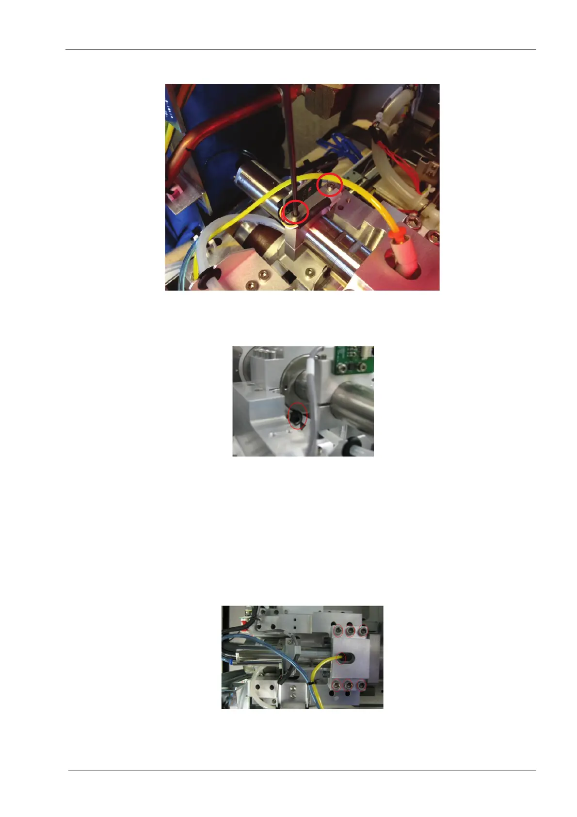
16. Remove the two 3 mm screws in the accelerometer sensor mount and lift the sensor
mount assembly out of the way.
Figure 201: Spindle seating screw
17. Remove the spindle seating screw from the inner face of the carriage.
18. Place the 22 mm flat open end key on the flat on the spindle motor closest to the
spindle and turn the motor anticlockwise to loosen the motor from the spindle.
19. Unscrew the motor from spindle.
Motors being returned to the supplier must have a cable attached. If the motor is being
replaced and the old cable is remaining installed, the new cable must be removed from the
new motor and installed on the old motor.
Figure 202: Saddle cap
20. Remove 6 screws securing spindle saddle cap to the carriage.