Chapter E: Basic repair procedures 2 Basic repair procedures
Technical manual Planmeca PlanMill 40 189
Figure 209: Slide spindle into housing and loosely install saddle cap
4. Slide the spindle into the housing.
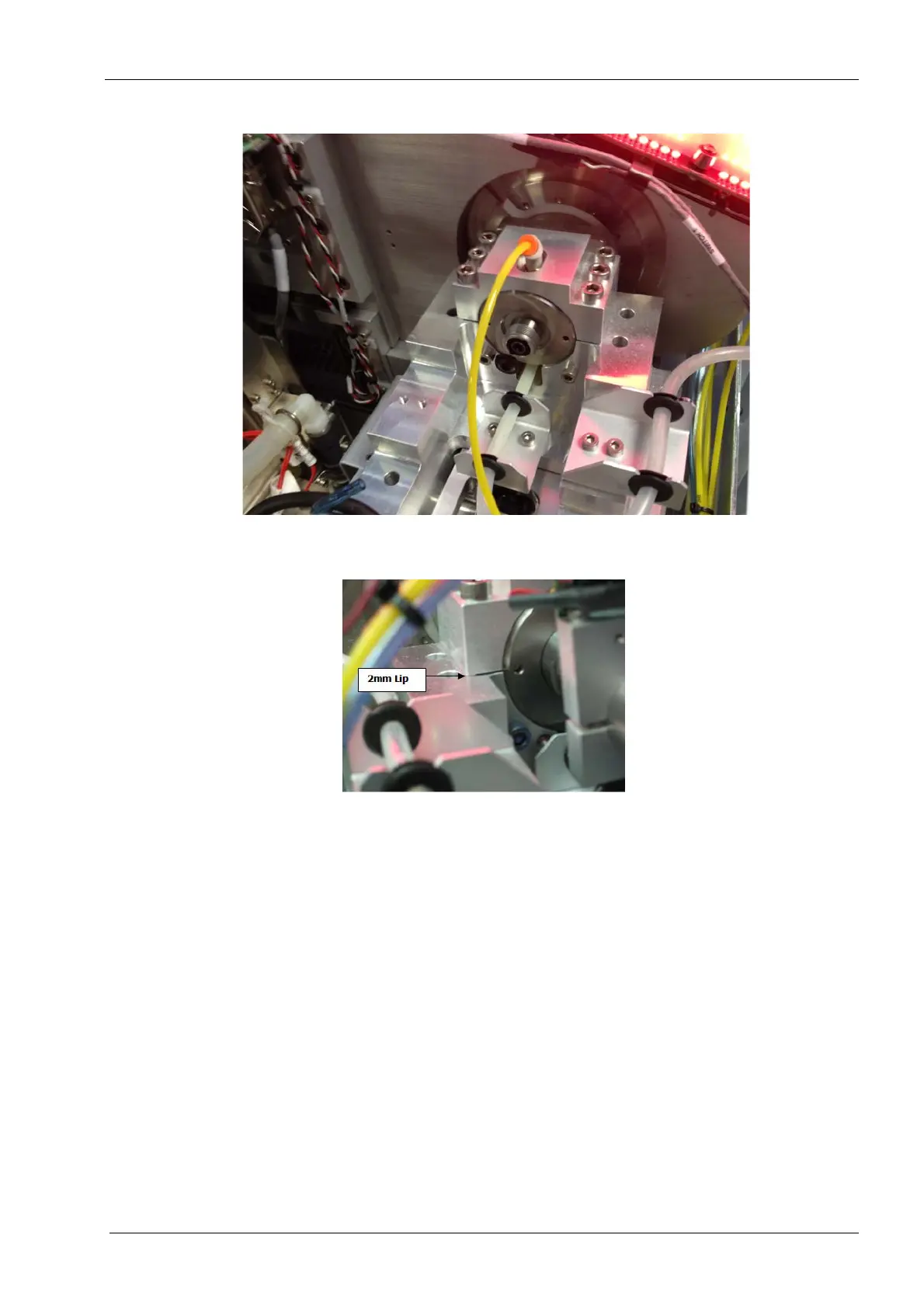
Figure 210: 2 mm lip should touch top of carriage
5. Loosely attach the 6 securing screws on top of the carriage ensuring that the one
touch fitting is centered in the hole in the saddle cap.
6. Ensure that there is a gap between the spindle saddle cap and the carriage
everywhere except for the 2 mm lip which should be flush with the carriage.