Chapter D: Troubleshooting 2 Troubleshooting
Technical manual Planmeca PlanMill 40 87
7. If your findings in the previous steps indicate the need for replacement parts such as
defective sensors or cables, obtain and install them and repeat the steps above to
verify the solution. Otherwise continue troubleshooting.
8. Verify power supply module LEDs are on. (Turn on the mill.)
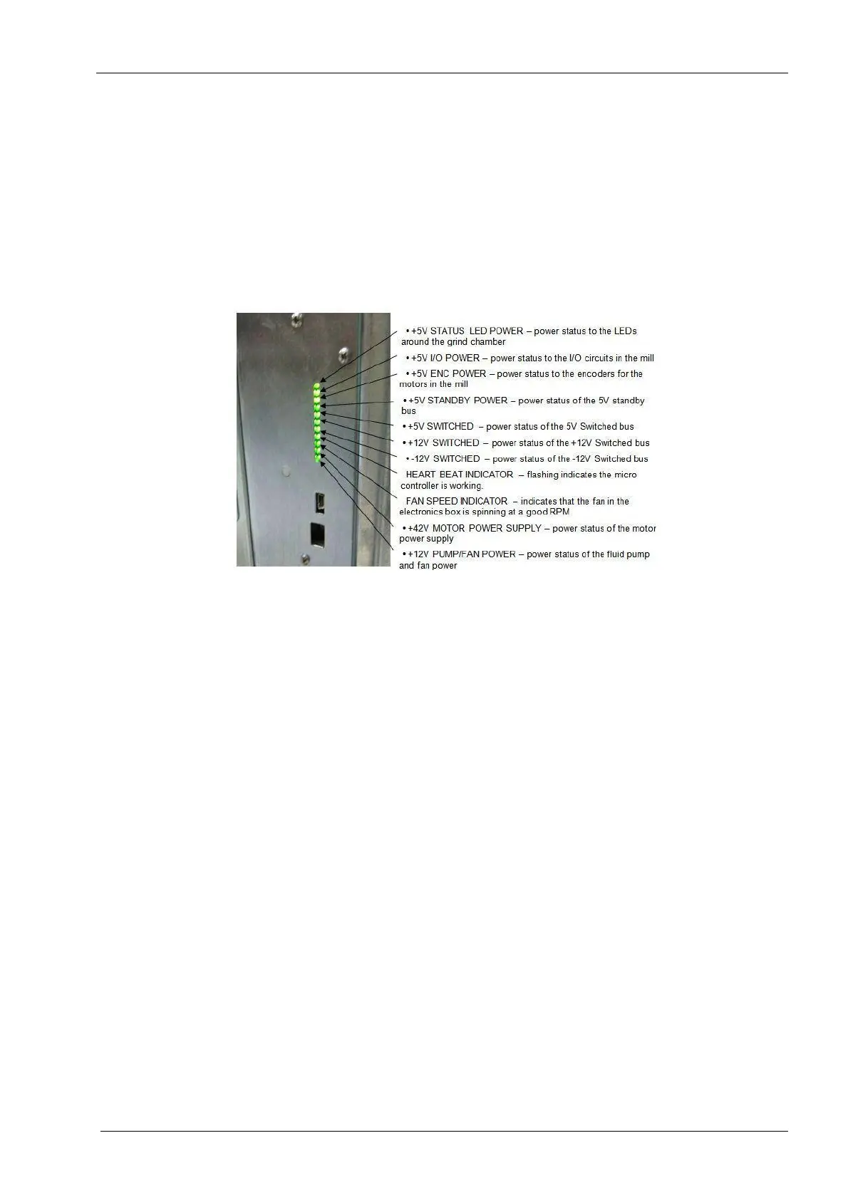
9. All 11 green power module status LEDs should be lit except for the 8th one down from
the top which should be flashing.
The following legend defines the meaning of each LED as displayed top to bottom.
Figure 68: Power supply LED status indications
10. If the 2nd LED from the top is not lit, then the home and end-limit sensors will not have
power. This is probably due to an electrical short circuit caused by a defective sensor
or cable.
11. If the 3rd LED from the top is not lit, then the servo motor encoders will not have
power. This is probably due to an electrical short in the circuit caused by a defective
servo motor, spindle motor, or cable.
12. If the 10th LED from the top is not lit, then the servo and spindle motors will not have
power. This is probably due to a defective 48 volt power supply.
13. Navigate the PlanMill 40 application to: Technician Console --> Motion.