Instrument Function
R&S
®
SMBV100A
207Operating Manual 1407.6062.32 ─ 08
"Ext Gated"
The pulse generator signal is gated by an external gate signal.
The signal is supplied via the PULSE EXT connector.
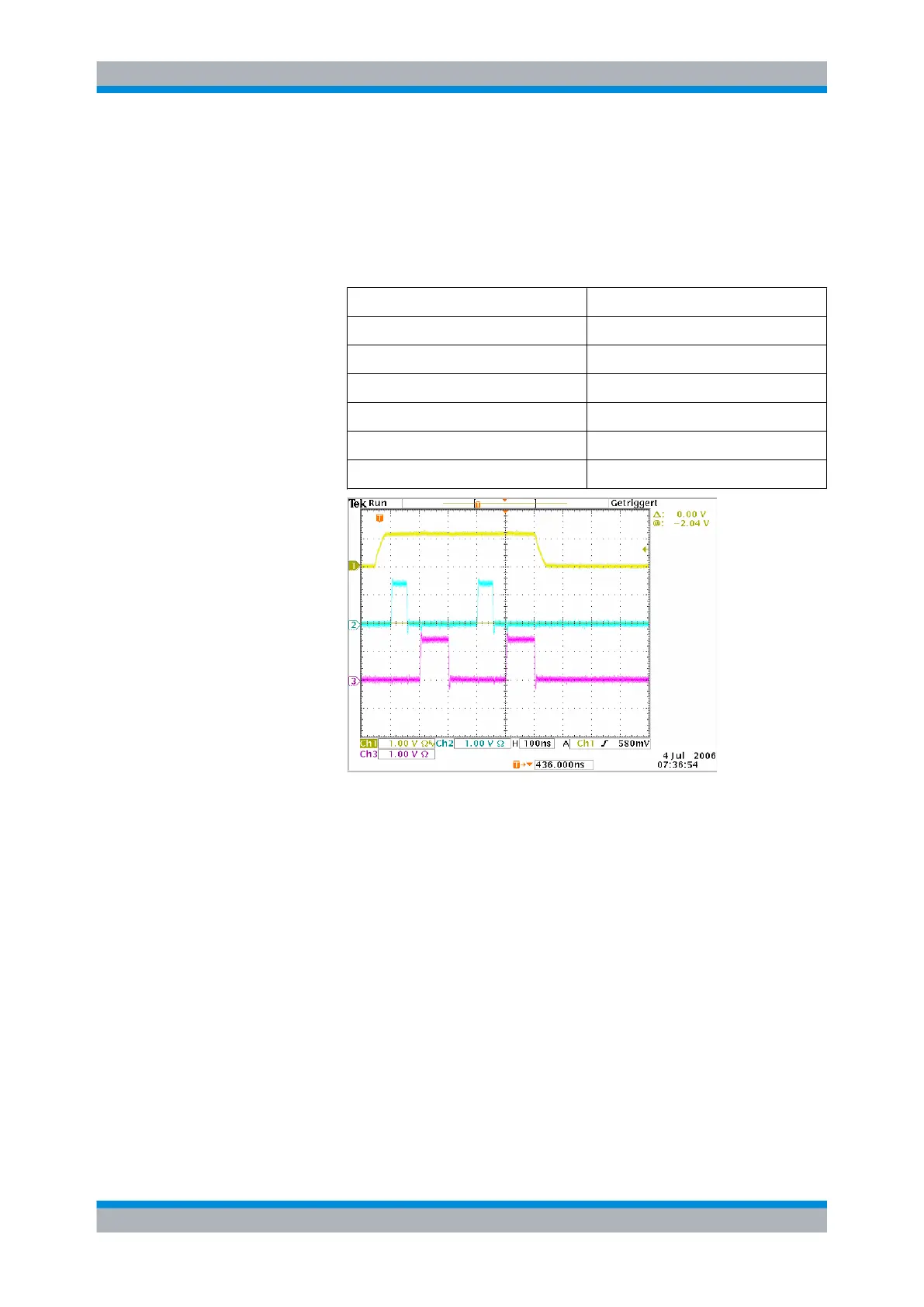
Example: Generation of pulse signals using trigger modes Ext
gated (Single Pulse)
The measurement were made using a 6-dB-attenuator.
Parameter Value
Trigger Mode Ext Gated
Double Pulse State Off
External Trigger Input Slope Positive
Pulse Delay 100 ns
Pulse Width 100 ns
Pulse Period 300 ns
Chan-
nel 1
= Indicates the external gate signal which is input at the PULSE EXT connector.
The signal is active when it is high (positive).
Chan-
nel 2
= Indicates the sync signal. The sync signal starts after a trigger delay of typically
50 ns (see specifications). It is repeated after the set pulse period of 300 ns
as long as the gate signal is active. The sync signal is output at the (PULSE)
SYNC connector.
Chan-
nel 3
= Indicates the pulse signal. The first pulse starts after the pulse delay of 100
ns. The second pulse starts after the set pulse period. They are output at the
(PULSE) VIDEO connector.
SCPI command:
[:SOURce<hw>]:PULM:TRIGger:MODE on page 689
External Trigger Input Slope - Pulse Generator
(External Trigger only)
Sets the polarity of the active slope of an applied trigger signal.
"Positive"
The pulse generator is triggered on the positive slope of the external
trigger signal.
RF Signal and Analog Modulations - RF Block

 Loading...


