inst_h3.fm
A31003-H3590-S100-7-7620, 06/2012
HiPath 3000/5000 V9, Service documentation
4-25
Nur für den internen Gebrauch Installing HiPath 3000
Installing HiPath 3800
Procedure
7
Warning
Never attempt to lift a system cabinet into the 19-inch cabinet without assistance.
Step Activity
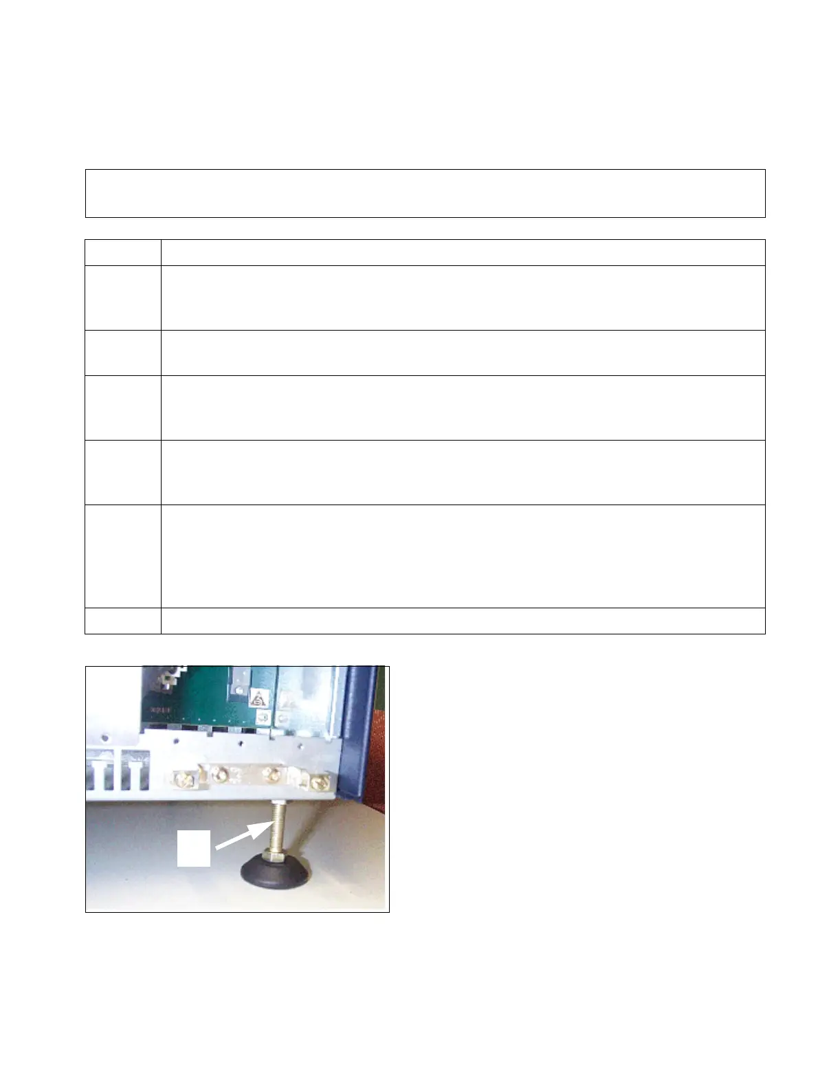
1. Remove all four cabinet feet from the system cabinet.
To do this, unscrew the lock nuts (Figure 4-11, A) on the cabinet feet using an open-
end wrench (wrench size = 13 mm). Unscrew cabinet feet completely.
2. Attach the two angle brackets (A in Figure 4-12) to the sides of the system cabinet
using the screws that have been supplied (four per bracket).
3. Attach a right-handed and a left-handed support bracket (B in Figure 4-12) in the
19-inch cabinet using the screws provided.
Note: the use of cabinet floors is not permitted to prevent overheating.
4. Lift the system cabinet into the 19-inch cabinet and sit the cabinet on the two sup-
port brackets (B in Figure 4-12). Slide the cabinet into the 19-inch cabinet until the
front edge of the system cabinet is flush with the front of the 19-inch frame.
5. Secure the system cabinet using the two angle brackets (A, in Figure 4-12) on the
frame of the 19-inch cabinet using the screws provided.
Please note that a minimum clearance of three height units must be observed be-
tween two stacked system cabinets. A minimum clearance of one free height unit
above a system cabinet is sufficient if a patch panel is to be installed, for example.
6. Repeat steps 1 to 5 if you want to install an expansion cabinet.
Figure 4-11 HiPath 3800 - Removing Cabinet Feet
A

 Loading...