inst_h3.fm
A31003-H3590-S100-7-7620, 06/2012
HiPath 3000/5000 V9, Service documentation
4-83
Nur für den internen Gebrauch Installing HiPath 3000
Installing HiPath 3800
4.1.11 Performing a Visual Inspection
Introduction
Before starting up the system, you must perform a visual inspection of the hardware, cables,
and the power supply. The procedure is shown in Table 4-9. The visual inspection must be per-
formed while the system is disconnected from the power supply.
Visual inspection procedure
7
Caution
Before beginning work, make sure that the system is grounded and disconnected
from the power supply.
Observe the measures for protecting electrostatically sensitive devices (see
Section 1.2.6, “Notes”).
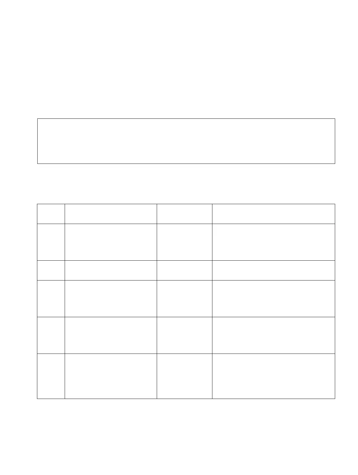
Table 4-9 Visual inspection procedure
Step Activity Resources/
Remarks
Action
1. Compare the slots of the
available boards with the
component mounting dia-
gram.
Board assign-
ment map
If necessary, correct the board config-
uration and notify the sales depart-
ment.
2. Check that all boards are
secure.
See Page 4-34 If necessary, plug the boards in again.
3. Check that a shielding cov-
er has been attached for all
boards with no connection
options in the front cover.
If necessary, replace missing shield-
ing covers (refer to Page 4-35).
4. Check whether the slots for
LUNA2 and for REALS (ba-
sic cabinet only) are cov-
ered by an outer panel.
If necessary, attach the outer panel
(see Page 4-37).
5. Check whether all system
cabinets have been sealed
at the rear with the connec-
tion and filler panels provid-
ed.
Get additional connection and filler
panels where required.

 Loading...