Basic information about the drive system
13.12 System rules, sampling times and DRIVE-CLiQ wiring
Drive functions
1018 Function Manual, 11/2017, 6SL3097-4AB00-0BP5
● For mixed operation of the servo control and vector V/f control operating modes, separate
DRIVE-CLiQ lines should be used for the Motor Modules.
● A Power Module with the CUA31/CUA32 should be connected to the middle or end of the
DRIVE-CLiQ line.
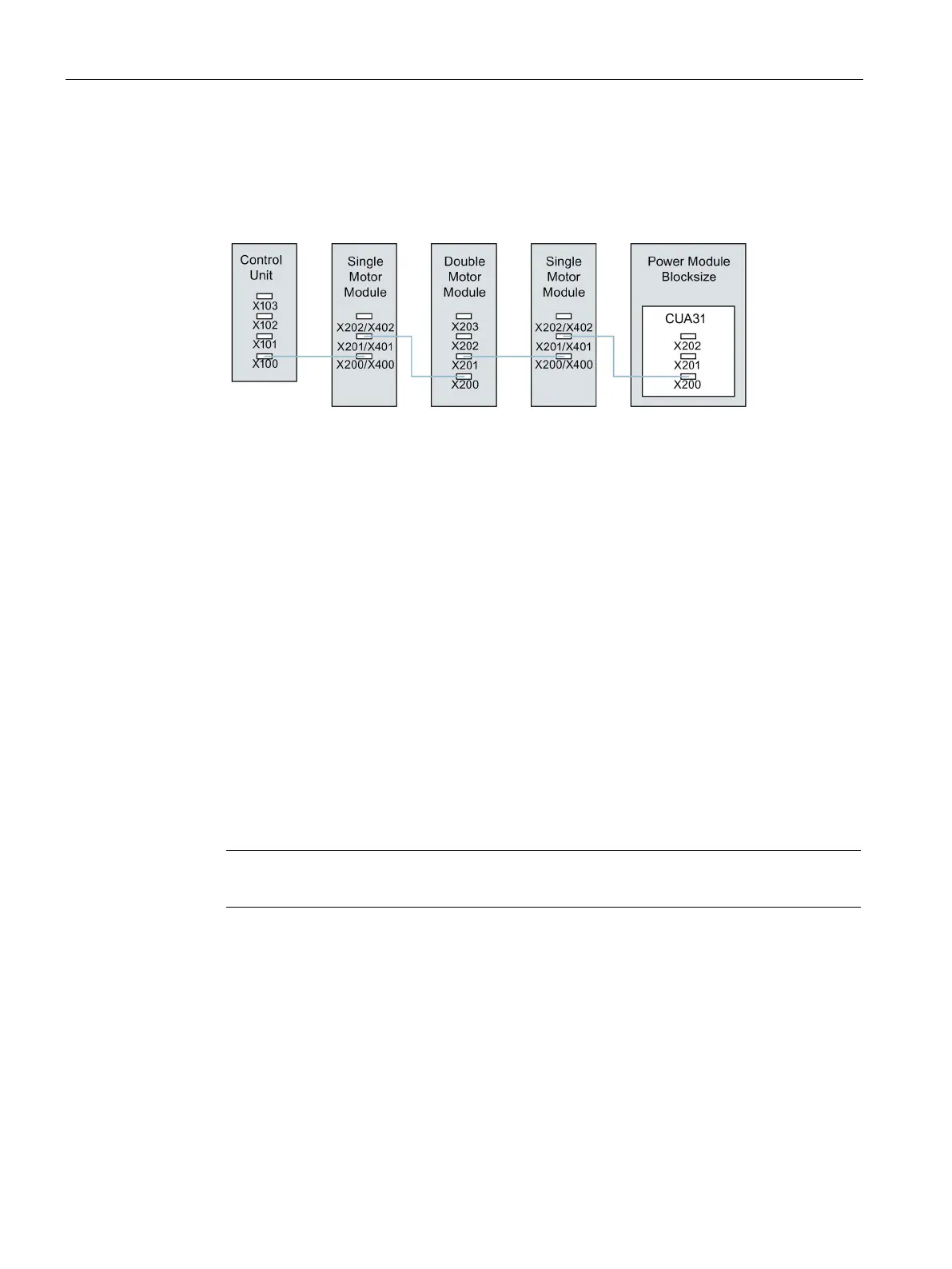
Figure 13-25 DRIVE-CLiQ line example
● The motor encoder or Sensor Module should be connected to the associated Motor
Module.
Connecting the motor encoder via DRIVE-CLiQ:
– Single Motor Module Booksize to terminal X202
– Double Motor Module Booksize motor X1 to terminal X202 and motor X2 to terminal
X203
– Single Motor Module chassis to terminal X402
– Power Module blocksize with CUA31: Encoder to terminal X202
– Power Module blocksize with CU310-2: Encoder to terminal X100 or to terminal X501
of a Terminal Module
– Power Module chassis to terminal X402
● If possible, Sensor Modules of direct measuring systems should not be connected to the
DRIVE-CLiQ line of Motor Modules, but rather to free DRIVE-CLiQ sockets of the Control
Unit.
Note
This restriction does not apply to star
-type connections for the Motor Modules.
 Loading...


