Basic information about the drive system
13.12 System rules, sampling times and DRIVE-CLiQ wiring
Drive functions
Function Manual, 11/2017, 6SL3097-4AB00-0BP5
1019
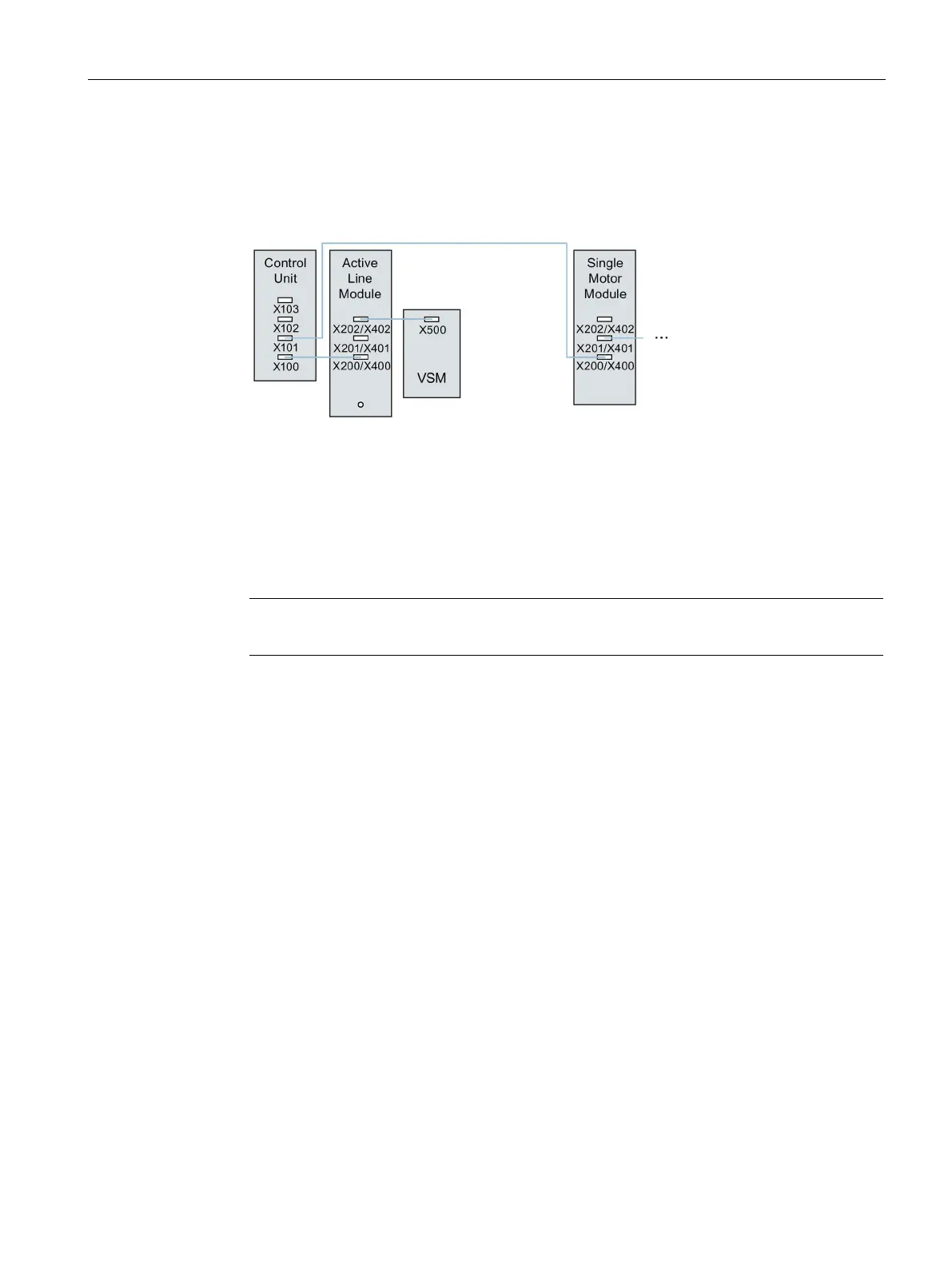
● When used for the infeed control, the Voltage Sensing Module (VSM) should be
connected to DRIVE-CLiQ socket X202 (booksize format) or X402 (chassis format) of the
associated Line Module.
Figure 13-26 Example of a topology with VSM for booksize and chassis components
● Terminal Modules should be connected to DRIVE-CLiQ socket X103 of the Control Unit in
series.
● If possible, Terminal Modules should not be connected to the DRIVE-CLiQ line of Motor
Modules, but rather to free DRIVE-CLiQ sockets of the Control Unit.
Note
This restriction does not apply to star
-type connections for the Motor Modules.
 Loading...


