Section 06 TRANSMISSION
Subsection 02 (DRIVE PULLEY)
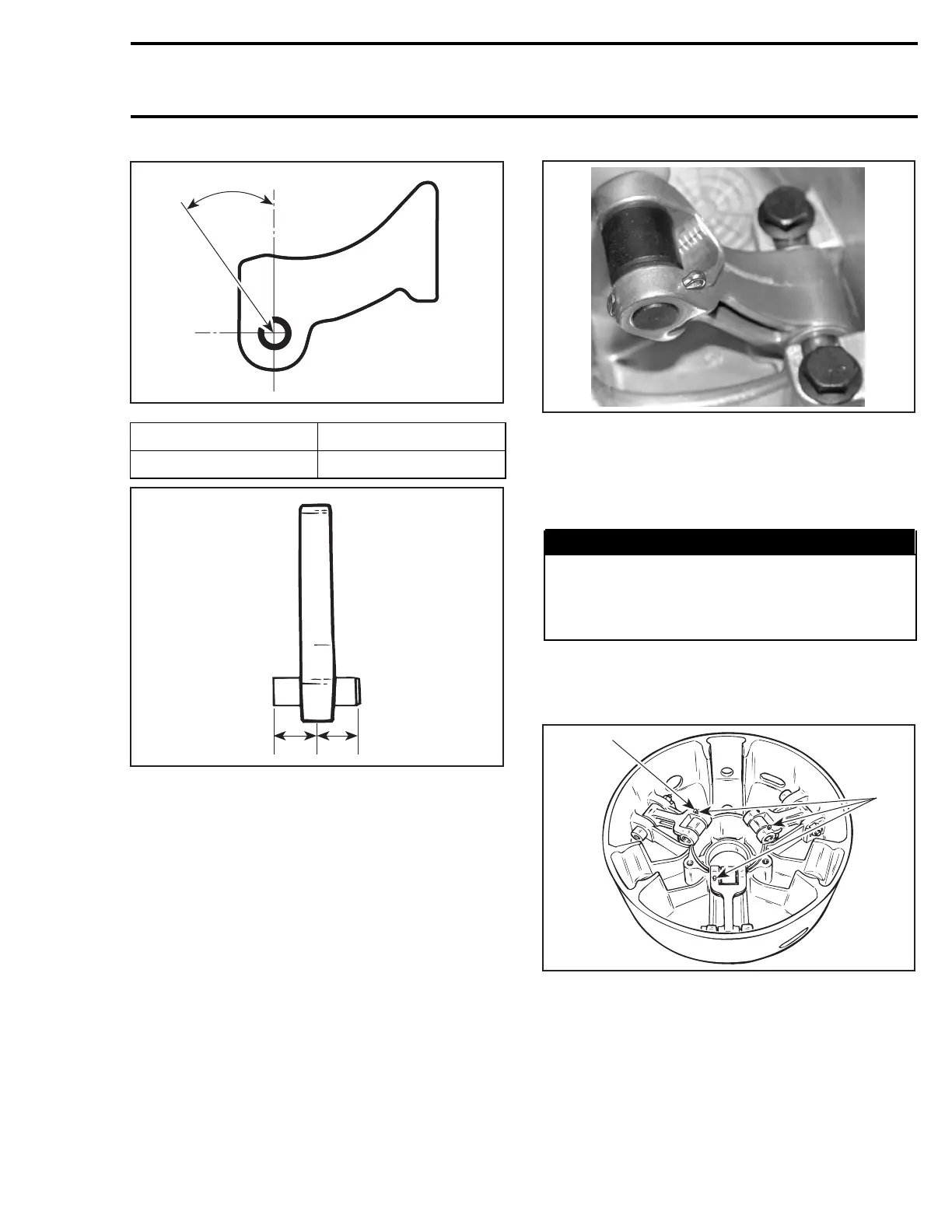
A16D2PB
A
MODEL ANGLE (A)
With TRA III 45 ± 3°
A16D09A
11
1. Equal distance
Torquescrewsto10N•m(89lbf•in).
9,11,13,14, Screw, Lever Ass’y,
Nut and Cotter Pin
NOTE: While installing lever assemblies make
sure that the curved sides of the levers are out-
wards as shown.
A32D1ZA
Always install lever assemblies so that cotter pins
are on the shown side. Besides install cotter pin
head on top when lever is sat at bottom of sliding
half. Bend cotter pin ends to sit perfectly against
lever.
WARNING
Whenever replacing centrifugal levers, al-
ways replace all 3 at the same time. Other-
wise, drive pulley misbalancing will occur
because of levers difference.
CAUTION: Lever assemblies must be installed
so that cotter pins are on the same side.
793 HO Engine Equipped Models Only
A16D0BA
1
2
TYPICAL
1. Head on top
2. All on the same side
mmr2004-Rev 221

 Loading...
