Section 07 ELECTRICAL SYSTEM
Subsection 05 (TESTING PROCEDURE)
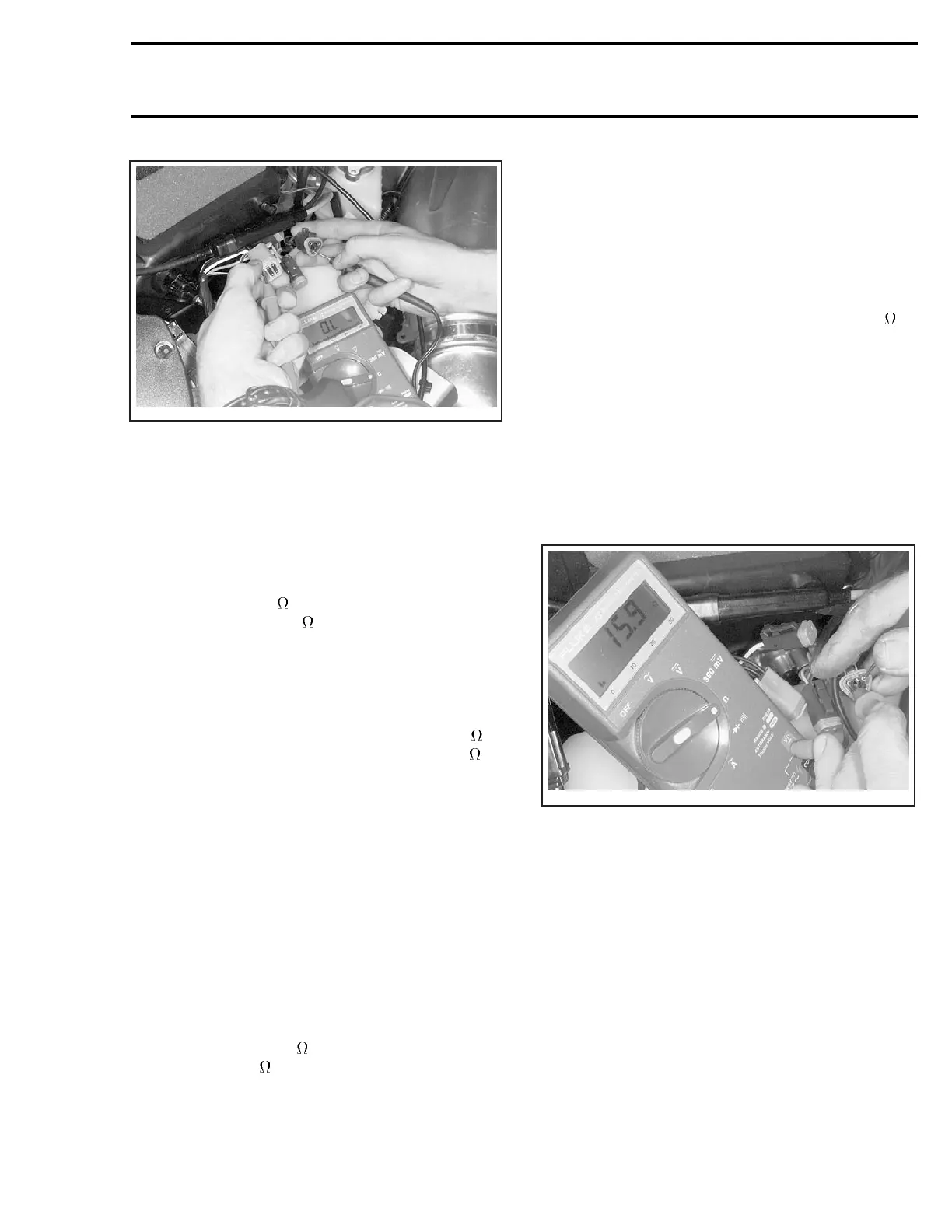
A32E0XA
TYPICAL
If readings are acceptable, go on to next step.
If readings are inadequate, individually check each
switch as follows.
Ignition Switch (if so equipped)
Disconnect switch housing. Using a multimeter,
check between MAG and GRD terminals if the cir-
cuit is open (0.L M
) in operating position and if
the circuit is closed (0
) in off position.
DESS Switch
All Models
Check using a multimeter by connecting probes
to BLACK/GREEN and BLACK/WHITE wires. The
multimeter should indicate a closed circuit (0
)in
operating position and a open circuit (0.L M
)in
off position.
If readings do not correspond to the above men-
tioned indications, replace switch.
If none of these verifications are conclusive, the
problem finds its source in the main wiring har-
ness. Proceed as follows:
Engine Cut-Out Switch
All Models
Unplug switch block connected to main wiring har-
ness. Check using a multimeter by connecting
probes to appropriate wires. Refer to correspond-
ing ignition and electrical system testing table in
this subsection. The multimeter should indicate
an open circuit (0.L M
) in operating position and
a close circuit (0
)inoffposition.
NOTE: For the next step, no switch must be con-
nected to the main wiring harness.
Disconnect all switches from the main wiring har-
ness and check the continuity of each wire by con-
necting probes to the end of wires of the same
color. Repeat with all other wires. It is impor-
tant to mention that all wires of the same color
within a given harness are connected together.
These wires should therefore have a closed cir-
cuit. On the other hand, BLACK and BLACK/YEL-
LOW wires must have an open circuit (0.L M
).
Repair or replace if necessary.
4. ignition Generator Coil Testing
Resistance Testing
– Disconnect housing between the magneto and
the MPEM.
– Connect multimeter probes to appropriate
wires and measure resistance. Refer to corre-
sponding IGNITION and ELECTRICAL SYSTEM
TESTING table in this subsection.
A32E0YA
TYPICAL
– Compare readings with those appearing in the
IGNITION table.
Voltage Testing
When manually starting the engine while the spark
plug is installed, the engine will tend to accelerate
beyond the compression point. This will result in
higher magneto output power.
– Disconnect housing between the magneto and
the MPEM.
– Connect multimeter probes to appropriate
wires. Refer to corresponding ignition and
electrical system testing table in this subsec-
tion. Bring the selector switch to V and the
scale to 00.0 Vac.
mmr2004-Rev 277

 Loading...
